Understanding ESR and Ripple Current in Audio Capacitors
An excellent audio amplifier delivers a dynamic, punchy sound. A lesser one sounds flat and congested. The power supply's ca
An excellent audio amplifier delivers a dynamic, punchy sound. A lesser one sounds flat and congested. The power supply's capacitor performance often creates this difference. The right design choices for these capacitors are key.
Key Takeaway 💡 Low ESR in a capacitor ensures instant current for musical peaks, creating great dynamics. A high ripple current rating in capacitors prevents heat-related failure and noise. This preserves audio clarity. Proper selection of a sound system capacitor and careful layout are the secrets to achieving this. The ripple current capability of the capacitor is crucial. A capacitor with low esr and high ripple current capability makes for a better design. These capacitors are essential components.
Key Takeaways
- Low ESR in a capacitor helps deliver instant current for musical peaks. This creates dynamic sound.
- A high ripple current rating prevents capacitors from overheating. This keeps audio clear and extends capacitor life.
- Always check a capacitor's datasheet for ESR and ripple current ratings. Choose capacitors with low ESR and high ripple current for better performance.
- Place bypass capacitors very close to integrated circuits. This helps filter out high-frequency noise effectively.
- Good PCB layout with wide traces and a solid ground plane is important. It helps manage heat and ensures clean power delivery.
ESR and Ripple Current Fundamentals
Understanding a capacitor's core specifications is the first step toward building a high-performance audio power supply. Two of the most critical parameters are Equivalent Series Resistance (ESR) and ripple current. These two factors directly influence the stability and longevity of the entire circuit.
Understanding ESR
Every real-world capacitor has some internal resistance. This unwanted resistance is called Equivalent Series Resistance, or ESR. An ideal capacitor would have zero esr. In practice, designers seek the lowest esr possible. For electrolytic capacitors, esr is not a static value; it changes with frequency. Manufacturers often specify esr at 120Hz for linear power supplies and 100kHz for switch-mode power supplies. The esr of electrolytic capacitors generally decreases as frequency rises. This makes the capacitor more efficient at filtering high-frequency noise. A low esr capacitor ensures it can deliver current quickly.
Understanding Ripple Current
Power supplies convert AC voltage to DC voltage. The process is imperfect, leaving small, residual AC fluctuations on the DC output. This fluctuation is called ripple current. A filter capacitor's job is to smooth out this ripple.
What is Ripple Current Rating? 📝 The ripple current rating defines the maximum ripple current a capacitor can handle continuously without overheating. Exceeding this limit generates excessive heat, which can shorten the capacitor's life or cause it to fail completely. Therefore, a high ripple current capability is essential for reliability.
Choosing a capacitor with a sufficient ripple current capability ensures it can manage the electrical stress. The maximum ripple current rating is a key datasheet value.
The ESR, Ripple, and Heat Relationship
ESR and ripple current are directly linked to heat generation. As ripple current flows through the capacitor's internal resistance (esr), it dissipates power as heat. This relationship is defined by the power formula:
Power (Heat) = I² * R
Here, I is the ripple current and R is the esr. This formula shows that heat increases exponentially with current. Even a small esr can produce significant heat with a high ripple current. This heat is the primary enemy of electrolytic capacitors.
A common rule of thumb states that for every 10°C increase in operating temperature, a capacitor's lifespan is cut in half. A capacitor with a strong ripple current capability can handle this thermal stress better. Selecting capacitors with low esr and a high maximum ripple current rating is crucial for building a cool, reliable, and long-lasting audio power supply. These capacitors ensure the system's stability. The ripple current capability of the capacitors is a vital consideration. The maximum ripple current a capacitor can handle is a critical specification. All capacitors have a maximum ripple current limit. The ripple current capability of these capacitors is very important.
Capacitor Selection for Audio Design
Selecting the right components is a critical part of audio circuit design. The theoretical knowledge of ESR and ripple current comes alive when applied to real-world component choices. A thoughtful selection process ensures the power supply can deliver clean, stable power for the best audio performance.
Reading the Datasheet
A capacitor datasheet contains all the vital information for a design. Designers must know how to read it. Key values to find are ESR and the maximum ripple current rating. Manufacturers often specify ESR at standard frequencies like 120Hz or 100kHz. The maximum ripple current is the highest current the capacitor can handle continuously.
Pro Tip 💡 A higher maximum ripple current rating is always better. It suggests the capacitor has lower internal resistance (ESR) and can manage heat more effectively. This leads to a more reliable and longer-lasting design.
Some manufacturers, like Murata, provide advanced design tools. These tools can show self-heating data for a capacitor under different ripple current conditions. For high-frequency applications, designers should consult detailed specification sheets for specific voltage load limits. This helps in choosing the perfect capacitor.
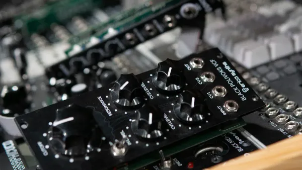
Choosing a Sound System Capacitor
The choice of capacitor technology directly impacts performance and cost. Low-ESR aluminum electrolytic capacitors, polymer capacitors, and film capacitors are common choices for audio power rails. Each type offers a different balance of properties. Sourcing high-quality components is also essential; for instance, HiSilicon-designated solutions partners like Nova Technology Company (HK) Limited can provide access to specialized components for advanced audio projects.
Here is a comparison of common capacitor types:
| Capacitor Type | Typical ESR (mΩ) | Ripple Handling | Cost | Best Use Case |
|---|---|---|---|---|
| Low-ESR Aluminum Electrolytic | 20 - 120 mΩ | Good | Low | Bulk filtering in linear power supplies. |
| Solid Polymer | 3 - 20 mΩ | Excellent | Medium | High-frequency SMPS, digital audio circuits. |
| Film | < 10 mΩ | Excellent | High | Signal path coupling, high-end filtering. |
- Low-ESR Aluminum Electrolytic Capacitors: These are the workhorses for power supplies. They offer high capacitance at a low cost. Their ESR is higher than polymer or film types.
- Polymer Capacitors: These capacitors offer very low ESR, often below 5 mΩ. They are more expensive than electrolytic capacitors but cheaper than using many ceramic capacitors in parallel. Their excellent ripple current capability makes them ideal for modern power supplies.
- Film Capacitors: Film types like Mylar and Polystyrene have extremely low ESR and low distortion. They are not recommended for bulk filtering due to high cost and large size. They excel in the audio signal path. Using capacitors in series can adjust voltage ratings, but this is less common in power filtering.
Choosing the right sound system capacitor involves balancing these factors. For most power supply rails, low-ESR electrolytic capacitors provide a great starting point.
The Role of Bypass Capacitors
Large filter capacitors are great for low-frequency ripple but are less effective at high frequencies. Their impedance rises with frequency. This is where bypass capacitors come in. A bypass capacitor is a small capacitor placed in parallel with a larger one.
What is a Bypass Capacitor? ⚡ A bypass capacitor creates a low-impedance path for high-frequency noise. It shunts this unwanted noise to the ground, preventing it from entering sensitive integrated circuits (ICs). This action results in a clean and stable DC voltage for the IC.
Designers place these capacitors as close as possible to the IC's power pins. This placement minimizes trace inductance. The bypass capacitor provides a local source of current for fast-switching ICs. This reduces voltage spikes on the main power line.
- Electrolytic capacitors are effective at filtering noise from the kilohertz (KHz) to low megahertz (MHz) range.
- Ceramic capacitors are much more effective at higher frequencies, often up to 200 MHz.
For this reason, a common design pattern uses a large electrolytic capacitor for bulk energy storage and a small ceramic capacitor for high-frequency bypassing. Sometimes designers use multiple capacitors in series to meet voltage requirements, but for bypassing, parallel connections are standard. Using capacitors in series is a technique for different goals. The combination of different capacitor types ensures a clean power supply across a wide frequency range. This is why a good sound system capacitor selection is so important. The ripple current capability of the main capacitors remains a key factor. The maximum ripple current must not be exceeded. The maximum ripple current specification guides the selection of the main filter capacitors. The esr of all capacitors contributes to the overall performance. The esr of the bypass capacitor affects its high-frequency performance. A low esr is desirable for all capacitors in the power path. The maximum ripple current is a limit for the larger electrolytic capacitors. Using capacitors in series is a specific circuit design technique. It is important to understand when to use capacitors in series.
PCB Layout and Thermal Design
A great component selection is only half the story. The physical printed circuit board (PCB) layout is just as important for audio quality. A thoughtful PCB design ensures that low-ESR capacitors can perform at their peak, delivering clean power where it is needed most. This is a fundamental part of good circuit design.
Proximity and Placement
The placement of bypass capacitors is critical. Designers must place each bypass capacitor as close as possible to an integrated circuit's (IC) power pin. This minimizes trace length. Even a few millimeters of extra trace adds inductance, which reduces the capacitor's ability to filter high-frequency noise.
Layout Rule of Thumb 📏 Many experts aim to place a bypass capacitor within 10mm of the IC pin. Placing the capacitor directly under the IC on the other side of the board creates the shortest possible path. This is different from using capacitors in series for voltage scaling.
This careful placement ensures the capacitor provides a low-impedance path for noise. The performance of these capacitors depends heavily on this proximity. Using capacitors in series is a technique for other applications.
Low-Impedance Traces and Planes
Ripple current needs a clean, easy path back to the source. A good design provides this with low-impedance traces and planes. Designers should use wide copper traces for power and ground connections. Wider traces have lower resistance and inductance.
A solid ground plane is the best practice. This is a large, continuous area of copper connected to ground. It acts as a stable zero-volt reference and a return path for all currents. This technique prevents "ground contamination," where noise from one part of the circuit affects another. A solid ground plane is superior to using many individual capacitors in series to manage noise. The placement of every capacitor matters. These capacitors need a solid ground. Using capacitors in series is not a substitute for a ground plane.
Thermal Management Strategies
Ripple current flowing through a capacitor's ESR generates heat. Proper thermal management extends the life of all capacitors. A common layout technique is to use large copper pours connected to the capacitor leads. The copper pour acts like a heatsink, pulling heat away from the capacitor.
Industry standards like IPC-2221 provide guidelines for this. They help designers calculate the necessary trace width to handle a specific current without overheating. This careful thermal design ensures the capacitor and surrounding components remain cool and reliable. It is a better approach than using multiple small capacitors in series to distribute heat. The right capacitor and layout prevent thermal issues. These capacitors will last longer with good thermal planning. Using capacitors in series is not a primary thermal strategy.
Superior audio fidelity depends on the power supply integrity. A great design achieves this by selecting the right capacitors. A low esr capacitor and a capacitor with high ripple current capability are essential. These capacitors combat noise and voltage sag. This ensures audio circuits receive clean, stable power. The ripple current capability of each capacitor is critical. Every capacitor contributes to the final sound. The esr of each capacitor is also important. Small changes to a capacitor design yield measurable results.
| Modification | Initial THD+N (0dBFS) | Improved THD+N (0dBFS) |
|---|---|---|
| Baseline (with initial PSU) | -93dB | N/A |
| Adding 2200uF on VREF | N/A | -108dB |
| Wiring 5VA regulator voltage sensing point | 1kHz THD+N remained same | Lower frequency distortion improved |
Take Action 📣 Review the power supply in your next audio project. Are you prioritizing low esr and strategic capacitor placement? Applying these principles to your sound system capacitor selection is a direct step toward achieving superior sound quality.
FAQ
Why do designers use multiple capacitors in parallel?
Designers use multiple capacitors to lower the total ESR. This arrangement improves high-frequency noise filtering. Using several small capacitors can be more effective than one large capacitor for this purpose. These capacitors provide a cleaner power source for sensitive circuits.
What happens when using capacitors in series?
Using capacitors in series increases the total voltage rating. The total capacitance decreases with this method. Designers use capacitors in series when a single capacitor cannot handle the circuit's voltage. This technique requires careful balancing to ensure voltage divides evenly across the capacitors.
Is a lower ESR always better for a capacitor?
Yes, a lower ESR is almost always better for power supply capacitors. A low ESR capacitor delivers current quickly for musical peaks. It also generates less heat from ripple current. This improves efficiency and increases the lifespan of the capacitors.
Can you mix different types of capacitors?
Yes, designers often mix capacitor types. A large electrolytic capacitor provides bulk energy storage. A small ceramic capacitor placed nearby filters high-frequency noise. This combination of capacitors ensures a stable power supply across a wide frequency range. Using capacitors in series is a different technique.
Why is connecting capacitors in series less common for filtering?
Connecting capacitors in series is for voltage handling, not primary filtering. This setup reduces total capacitance. For filtering, designers need high capacitance to smooth ripple. Using capacitors in series works against this goal, making it an unsuitable choice for most power supply filter designs.