DC Controller PCB Assembly: Component Selection and Design Optimization for Power Management Systems
Engineers get the best results in dc controller pcb assembly by picking the right parts and planning the design well. Each pcb in a dc controller pcb assembly needs to help with control and efficiency.
Engineers get the best results in dc controller pcb assembly by picking the right parts and planning the design well. Each pcb in a dc controller pcb assembly needs to help with control and efficiency. This makes sure the system works well and lasts a long time. Choosing good parts and a smart pcb layout affects how the system works, how it can grow, and how easy it is to put together. Good design and control in dc assembly help power management systems handle tough jobs and keep working the same way every time.
Key Takeaways
-
Picking the best parts and making a good PCB layout helps power control, makes things work better, and keeps the system safe. Good heat control and putting parts in the right spots help the PCB stay cool and last longer. Following rules and checking quality keeps the assembly safe and working well for a long time. Using machines and testing cuts down on mistakes, makes things faster, and keeps the PCB assembly good. New materials and design tools help make power management systems stronger, lighter, and work better.
Power Management Systems Overview
Key Functions
Power management systems help control how much power devices use. They help devices save energy and still work well. These systems can put devices in different power states. Some states are active, sleep, hibernate, and off. Devices pick a state based on what they need to do. For example, a server can use Balanced, High Performance, or Power Saver modes. These modes change how much power the processor uses. Processor performance states, called P-states, change the CPU speed for each job. Hardware-controlled P-states can react very fast, in about 1 millisecond. Some systems use special settings to balance saving power and working fast. These settings can be set from 0 to 100.
Thermal throttle management keeps devices from getting too hot. Devices like NVMe SSDs slow down if they get too warm. They can also go into deep sleep and use very little power, like 4mW. Core parking helps by turning off some CPU cores to save power. Tools like the powercfg /energy command help find power problems. All these features help systems stay efficient and work well.
Tip: You can set the lowest and highest processor performance states. This can limit CPU speed and save power without making things slower.
Application Areas
Power management systems are used in many industries. Data shows they are used in Oil and Gas, Marine, Chemicals and Pharmaceuticals, Paper and Pulp, Metals and Mining, Utilities, and Data Centers. Each industry uses these systems to control energy and make things more reliable. For example, data centers need good power control to keep servers working and avoid problems. Utilities use these systems to balance how much power is used and made. The market keeps track of sales, money earned, and growth for each area from 2018 to 2028. This information helps companies see where power management systems help the most.
A table below shows some common application areas:
|
Industry |
Use of Power Management Systems |
|---|---|
|
Oil and Gas |
Equipment control, safety |
|
Marine |
Shipboard power distribution |
|
Chemicals & Pharmaceuticals |
Process automation, safety |
|
Paper and Pulp |
Machine power optimization |
|
Metals and Mining |
Heavy equipment power control |
|
Utilities |
Grid management, load balancing |
|
Data Centers |
Server power efficiency |
These examples show that power management systems help many industries. They make power use better and keep systems steady.
System Requirements
Power Ratings
Every dc controller pcb assembly must follow strict power rules. This keeps the system safe and working well. Engineers pick parts that fit the needed dc load and voltage. The power pcb must handle high and normal current without getting too hot. Designers figure out the highest voltage and current for each pcb part. They also make sure the power supply can support all devices. If the power pcb cannot carry enough current, it could fail or be unsafe. Using the right size copper traces and power planes helps control heat and voltage loss. IPC-2152 gives advice for copper sizing. This keeps power flow safe and stops damage.
Environmental Factors
The environment changes how well a dc controller pcb assembly works. High heat, moisture, and dust can cause the power pcb to break. Designers use materials with high Comparative Tracking Index (CTI) ratings. These materials stop electrical breakdown. They also plan for airflow and cooling to keep the system safe. The power pcb must work in normal and tough places, like factories or outside. Small spaces need compact layouts, so engineers balance size and heat control. Good design helps the dc controller pcb assembly stay reliable even in hard conditions.
Regulatory Needs
Rules help keep people and equipment safe in every dc controller pcb assembly. Groups like IPC and ANSI make rules for safety, heat control, and ESD protection. The table below shows important standards and what they do in power pcb design:
|
Standard / Guideline |
Purpose / Requirement |
Relevance to DC Controller PCB Assembly |
|---|---|---|
|
IPC-2221 |
Defines creepage and clearance distances between conductors |
Prevents ESD and electrical arcing by ensuring safe spacing based on voltage and environment |
|
IPC-2152 |
Recommends copper pour sizing and power plane design |
Controls current carrying capacity and limits temperature rise in PCB traces |
|
IPC-6012 & IPC-A-600 |
Sets reliability classes (Class 2, Class 3) for PCB quality |
Ensures performance and durability under electrical and thermal stress |
|
UL/IEC Safety Standards |
Establishes essential safety requirements for electrical devices |
Prevents hazards such as electrical shock, fire, and component failure |
|
Specifies requirements for ESD control programs |
Protects electronic assemblies from electrostatic discharge damage |
|
|
IEC 60950-1 |
Specifies minimum creepage and clearance distances |
Ensures isolation and safety in high-voltage PCB areas |
|
Material CTI Ratings |
Comparative Tracking Index for insulation materials |
Guides selection of PCB materials to resist electrical breakdown and surface tracking |
Note: Following these rules helps the dc controller pcb assembly pass checks and work safely in any power management system.
Designers also think about cost, future changes, and load needs. A good power pcb can be upgraded and changed without big redesigns. This saves time and money and still meets all safety and reliability needs.
Component Selection in DC Controller PCB Assembly
Core Components
Engineers start by picking the main parts for power control. These parts are MOSFETs, diodes, capacitors, inductors, and microcontrollers. Each part must fit the voltage and current needs of the power pcb. Good parts help the system work well and last longer, even in tough places.
The parts you choose change how well the assembly works. For example, MOSFETs with low on-resistance make less heat. This helps the power stage work better. Capacitors with high ripple current ratings keep voltage steady and block noise. Inductors with the right saturation current stop power loss and overheating. Microcontrollers help control and watch over the dc controller pcb assembly.
How well the assembly works also depends on solder joints and pcb layout. The table below shows how different assemblies do under stress:
|
Assembly |
Solder Joint |
Crack Length (μm) |
Diameter (μm) |
% Crack Length |
Failure Status |
Temperature Cycling Lifetime (h) |
Random Vibration Lifetime (h) |
Failure Prediction Accuracy |
|---|---|---|---|---|---|---|---|---|
|
D1 |
A16 |
142.36 |
453.68 |
31.37% |
Yes |
498,104.2 |
65.7 |
98.5% (edge joints) |
|
D2 |
A1 |
112.57 |
438.64 |
25.66% |
Yes |
194,894.2 |
51.0 |
- |
|
D3 |
A1 |
19.79 |
444.39 |
4.45% |
No |
16,544,422.6 |
312.0 |
- |
|
D4 |
A16 |
0 |
441.21 |
0% |
No |
64,199.3 |
3,106.6 |
- |
|
A |
A28 |
15.40 |
601.10 |
2.56% |
No |
6,655.7 |
7.05 × 10^7 |
- |
Note: If the crack length is more than 25% of the joint, it fails. High prediction accuracy, like 98.5%, helps engineers make better designs.
The chart below shows how long assemblies last with heat and shaking. This shows why good parts and strong assembly matter.
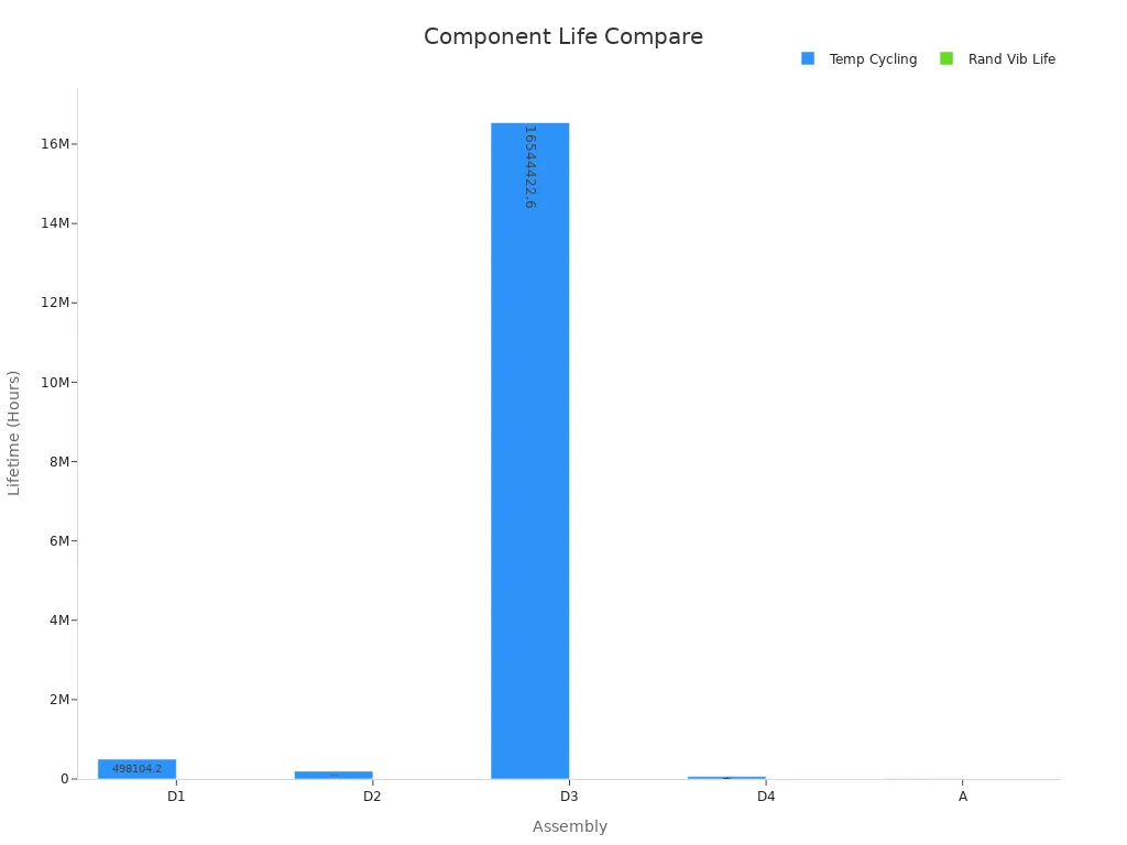
Engineers need to think about these things to get good results and make sure the assembly lasts a long time.
PMICs and DC-DC Converters
Power Management ICs and DC-DC converters are very important in power supply design. They control voltage, manage current, and protect sensitive parts. Picking the right ones changes how well the system works.
Switching regulators are used a lot because they are very efficient, up to 95%. Linear regulators are easier to use but not as efficient. They are better for low-noise jobs. The table below shows the differences:
|
Parameter |
Linear Regulator Characteristics |
Switching Regulator Characteristics |
|---|---|---|
|
Efficiency |
Generally low, approximated by VO/VIN ratio |
High efficiency, approximately 95% |
|
Output Power |
Typically several watts, limited by thermal design |
Can handle large power levels |
|
Noise |
Low noise output |
Generates switching noise |
|
Design Complexity |
Simple design |
More complex design |
|
Bill of Materials |
Low component count |
Higher component count |
|
Cost |
Lower cost |
Relatively higher cost |
Engineers pick PMICs and converters by looking at voltage range, output accuracy, and current. They also check dropout voltage, how fast it reacts, and how well it blocks ripple. Synchronous switching converters are the most efficient, which is important for saving power.
Tip: Make sure the converter’s output current matches the load. This stops overheating and keeps power steady. Always check the temperature rating for safe use.
Good parts here help the power supply work well and keep the system steady in all conditions.
Sourcing and Reliability
Getting good parts from trusted suppliers is very important. Teams look at how reliable suppliers are, how fast they deliver, and if the parts are good. About 35% of teams say getting parts is a top job because it affects how well the assembly works. Hard sourcing steps make problems for 17% of teams, which can cause trouble in making the power pcb.
Automation helps 33% of leaders see how suppliers are doing. This makes it easier to check if parts come on time. Suppliers say buyers care about price, but quality and reliability are still very important. Over half of suppliers, about 53%, give extra info to help engineers check if parts are good.
The table below lists important things to check when picking suppliers:
|
Vendor Performance Metric |
Description and Relevance to Component Dependability Evaluation |
|---|---|
|
Delivery lead times |
Shows if suppliers send parts on time. |
|
Pricing competitiveness |
Checks if prices are good and fair. |
|
Communication time lags |
Looks at how fast suppliers answer questions. |
|
Substitutions made |
Counts how often parts are changed. |
|
Quality of the products supplied |
Shows if the parts work well and last. |
|
Number of back orders |
Tells if there are delays or missing parts. |
|
Frequency of price changes |
Checks if prices change a lot. |
|
Compliance with negotiated terms |
Makes sure suppliers follow the rules you agreed on. |
Note: Engineers should always check if suppliers follow the rules and track delivery to keep the assembly reliable.
Getting good parts from trusted sources, picking the right parts, and building strong power stages help every dc controller pcb assembly meet high standards for performance, efficiency, and reliability.
Design Optimization and Efficiency
Layout and Placement
Engineers know that smart layout and placement are very important. Good layout helps the power pcb work better and last longer. Putting high-power parts near the edges helps heat leave faster. This also lets air move better and keeps things cool. It stops hot spots from forming on the board. When high-power and low-power parts are kept apart, it protects weak circuits from heat.
A good layout also makes signals travel faster and with less noise. If high-speed parts are close to connectors, signals move up to 20% quicker. Leaving at least 5 mm of space around high-power parts keeps them cooler. This can make parts last twice as long. The table below shows how layout choices help with heat and board performance:
|
Performance Metric / Strategy |
Impact on Heat Dissipation and Board Performance |
|---|---|
|
Copper foil area increased to 1.5× component size |
Big drop in part temperature because heat leaves faster |
|
Part temperature drops by 4.8°C; heat spreads out better |
|
|
Placement of high-power components near PCB edges |
Heat leaves faster, fewer hot spots, better airflow |
|
Separation of high-power and low-power components |
Stops too much heat in one place, helps cooling |
|
Placing high-speed components near connectors |
|
|
Maintaining at least 5 mm clearance around high-power components |
Stops hot spots, can double how long parts last |
Engineers use these layout tricks to meet tough power and efficiency goals in every dc controller pcb assembly.
Thermal Management
Thermal management is key for making a power pcb work well. High heat can break parts and slow down the system. Engineers use copper pours and thermal vias to move heat away from hot spots. Tests show these features can lower part temperature by about 10°C when the current is 1 A. Cooler parts last longer and work better.
Putting hot parts near the edge or by heat sinks helps heat leave the board. Using a 6×6 thermal via array can lower part temperature by 4.8°C and spread heat more evenly. Engineers always check if the power pcb can handle the highest current without getting too hot. They also use airflow and heatsinks to help cool high-power dc controller pcb assemblies.
Tip: Always check the temperature of important parts during tests. Finding hot spots early stops problems and keeps the system working well.
EMI Control
Electromagnetic interference, or EMI, can mess up signals and make the dc controller pcb assembly work worse. Engineers design carefully to keep EMI low and follow the rules. They keep fast signal lines short and away from sensitive areas. Ground planes and shields help block unwanted noise.
Designers also keep power and control circuits apart to stop cross-talk. They put decoupling capacitors near power pins to block high-frequency noise. These steps protect the assembly from outside noise and keep control systems steady. Meeting EMI rules makes sure the power pcb works well anywhere.
Design Efficiency
Design efficiency means using every part of the assembly in the best way. Engineers use computer tools to test designs before building the pcb. A study with over 350,000 tests showed that smart design steps, like central-composite designs, make the system work better. These steps help engineers balance power, speed, and cost.
Engineers use design for manufacturability (DFM) to make building and testing easy. They pick standard part sizes and clear labels to speed up making the board. Using sensors for predictive maintenance cuts down on repairs and keeps things running. Custom controls, like lights that change for each user, also help the system work better.
Note: Good design makes it easy to upgrade later. A flexible power pcb saves time and money when adding new features or more power.
Engineers who use these design steps help every dc controller pcb assembly meet tough efficiency goals and work well in hard jobs.
Manufacturing & Testing
Assembly Methods
The pcb assembly starts with putting parts on the board. Machines called pick-and-place do most of this work. They make things faster and help stop mistakes. People watch the machines and check for problems. Soldering holds each part onto the pcb. This can be done by reflow or wave soldering. The team uses surface mount technology for small parts. They use through-hole methods for bigger parts.
First Pass Yield, or FPY, is a very important number in pcb assembly. FPY tells how many boards are good the first time. If FPY is high, the process works well and there is less waste. Things like how hard the board is, how well people are trained, and if machines work right all change FPY. When FPY goes up, more boards are made and costs go down.
Quality Control
Quality control is a big part of making pcbs. Teams do many checks to find problems early and keep things running well. They look at how much solder paste is used and how tall the solder joints are. They also check if parts are the right size. Machines like AOI and X-ray help find hidden problems. The table below shows important quality checks and what they should be:
|
Quality Control Indicator / Failure Rate |
Description / Target Value |
Validation Method / Test |
|---|---|---|
|
Defect Rate per Million Units (DPMU) |
Target under 100 DPMU |
Statistical Process Control (SPC) |
|
Solder Paste Volume |
0.8 to 1.2 mm³ per pad |
In-process inspection |
|
Solder Joint Height Control |
±0.1 mm control limits |
SPC alerts |
|
Supplier Component Tolerances |
±1% variance for resistors |
First Article Inspection (FAI) |
|
Functional Testing |
Output voltage stability ±0.1V |
Automated tests |
|
Burn-In Testing |
24-48 hours at high temp/voltage |
Early failure detection |
|
Boundary Scan Testing |
JTAG for digital connectivity |
Detects stuck-at faults |
|
Environmental Stress Tests |
Thermal cycling, humidity, vibration |
Exposes defects |
|
Advanced Diagnostic Tools |
X-ray, In-Circuit Testing |
Failure mode analysis |
|
International Standards |
IPC-TM-650, IPC-6012, MIL-STD-202/883, JEDEC, ISO |
Quality frameworks |
Quality control steps help teams find problems before customers get the product. This makes the pcb more reliable and work better every time.
Validation
Testing and validation make sure each pcb assembly is safe and works right. Teams do tests to check voltage, current, and logic signals. Stress tests like heating and shaking show if the board can handle tough jobs. Burn-in testing runs the board hot and with high voltage for up to 48 hours to find weak parts.
Testing and validation also mean following rules like IPC-6012D. Passing these tests shows the board can be used in real life. Teams use microsectioning and stress tests to find weak spots and guess how long the board will last. These steps help keep quality and reliability high from the start to when the board is used.
Testing and validation help protect the work done in design and making the board. They make sure each pcb assembly will work well in any power management system.
Trends in DC Controller PCB Assembly
New Materials
Engineers are using new materials to build dc controller pcb assembly. These new materials make each pcb lighter and stronger. Some boards now use high-temperature laminates. These laminates help the assembly work in hot places without breaking. Other materials, like low-loss dielectrics, help signals move faster and with less noise. This makes the power system work better and more reliably.
Manufacturers use copper that is more pure. This copper lowers resistance and lets the dc controller pcb assembly carry more current. Some teams use flexible substrates. These let the pcb bend and fit into small spaces. New coatings protect the assembly from water and dust. All these changes help the assembly last longer and work well in tough jobs.
-
In the future, pcb hardware and layout will be smarter and cheaper.
-
New technology will help make low-cost, high-performance pcbs and hardware modules.
-
Using software will help manage data and improve results for users.
-
Hardware and software together will change the security industry and the dc controller pcb assembly market.
Automation
Automation is now very important in dc controller pcb assembly. Machines put parts on the pcb quickly and accurately. This helps stop mistakes and keeps the assembly high quality. Automated inspection tools check each assembly for errors. These tools find problems early, so teams can fix them before shipping.
Software now helps control the whole assembly process. It tracks every step and collects data. This data helps engineers make better designs and find weak spots. Automated systems also help with testing. They check every dc controller pcb assembly to make sure it meets power and safety rules.
Engineers use automation to save time and money. They can build more assemblies faster. This helps companies keep up with the need for new dc power systems. Automation also makes it easier to update designs when new parts or materials are used.
Engineers make sure the assembly works well by using clear steps. They pick parts carefully and plan the design. They use automated optical inspection to check for mistakes. This tool helps cut down on fixing errors by half or more. Making the design simpler also helps. It can make assembly faster and reduce mistakes by up to 30%. The table below shows how each step helps the assembly and makes it better:
|
Actionable Step |
Benefit / Impact on Assembly and Design |
|---|---|
|
Automated Optical Inspection (AOI) |
Reduces rework by 50% or more |
|
Design Simplification (DFA) |
Cuts assembly time and defects by 15–30% |
|
Lead Time Reduction |
Speeds up assembly and design cycles |
|
Component Sourcing Optimization |
Lowers costs and supply risks |
|
Automation of High-Volume Tasks |
Cuts labor costs and errors |
|
Energy-Efficient Processes |
Reduces energy use and improves performance |
|
Modular Fixturing |
Maximizes equipment use in assembly |
|
Data Analytics Process Improvements |
Lowers costs and boosts design quality |
Teams make sure every design fits what the system needs. They work to save energy and time. They watch for new ideas and follow the best ways to build. This helps keep the assembly and how it works at a high level.
FAQ
What is the main goal of DC controller PCB assembly in power management systems?
The main goal is to control and share power in a smart way. Engineers design the assembly to keep things working steady and safe. This helps power management systems work well in many places.
How do engineers choose components for a DC controller PCB?
Engineers pick parts by looking at voltage, current, and how long they last. They check if suppliers are good and test parts to see if they are strong. This makes sure the assembly can handle what power management systems need.
Why is PCB layout important for power management systems?
PCB layout helps control heat, keeps signals clear, and makes the system last longer. Putting parts in the right spots helps keep things cool and quiet. This makes power management systems work better and last longer.
What tests ensure the quality of a DC controller PCB assembly?
Teams use machines to check for mistakes and run tests to see if everything works. They also do stress tests to find weak spots early. These checks make sure the assembly is safe and works well.
How does automation improve PCB assembly for power management systems?
Automation makes putting parts on the board faster and checks for mistakes. Machines help stop errors and keep the quality high. Automated systems also collect data to help make better designs later.