How Coupling Capacitors Prevent Signal Distortion in Electronic Systems
You rely on coupling capacitors to keep your electronic circuits running smoothly. These components block unwanted DC while
You rely on coupling capacitors to keep your electronic circuits running smoothly. These components block unwanted DC while letting AC signals pass, which helps protect signal integrity. You notice improved voltage stability and less noise in your designs when you use them correctly.
- Coupling capacitors reduce noise voltage that can appear between conductors in a circuit.
- Adding a grounded conductor, like a Faraday shield, often lowers noise and keeps voltage steady.
Engineers, students, and electronics enthusiasts all benefit from understanding how these capacitors support system performance.
Key Takeaways
- Coupling capacitors block DC signals while allowing AC signals to pass, ensuring clear signal transmission in electronic circuits.
- Proper placement of coupling capacitors near circuit components reduces noise and maintains voltage stability, enhancing overall performance.
- Choosing the right capacitance value is crucial; it affects how your circuit handles different frequencies and prevents distortion.
- Combining capacitors of different values helps cover a wide frequency range, improving signal integrity and reducing unwanted noise.
- Always check for DC offset in signals before sending them to sensitive parts of your circuit to protect components and improve quality.
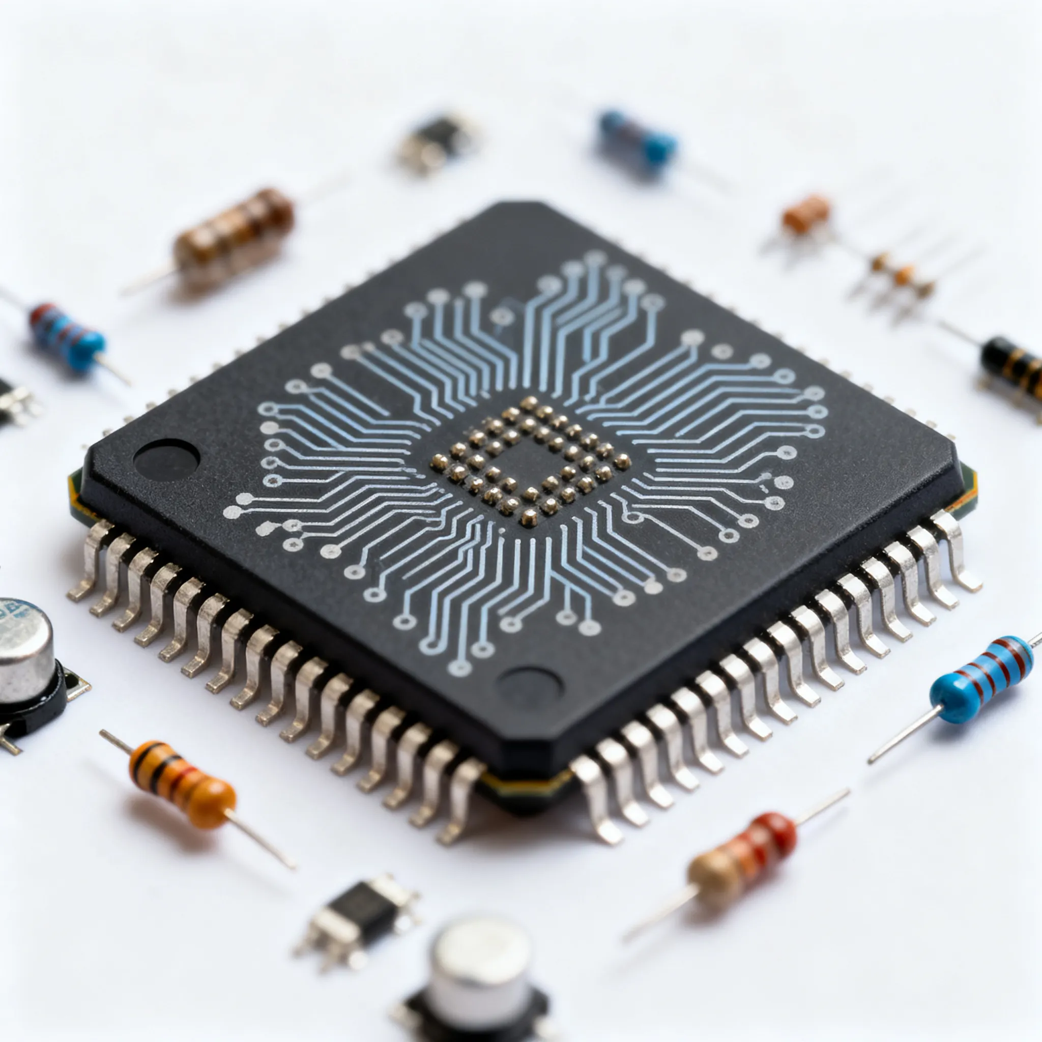
Coupling Capacitors in Electronic Circuits
Blocking DC, Passing AC
You often see coupling capacitors in electronic circuits because they help you control how signals move between different parts of a system. These capacitors let AC signals travel from one stage to another, but they stop DC signals. This action keeps each part of your circuit at the right voltage level. When you connect a capacitor between two stages, it charges up if there is a DC voltage. After charging, it blocks any more DC from passing through. However, when an AC signal comes along, the capacitor charges and discharges quickly, letting the signal move forward.
Tip: In audio circuits, coupling capacitors protect your speakers by blocking harmful DC. In radio frequency (RF) systems, they keep DC away from antennas but allow high-frequency signals to pass.
You can see the main functions of coupling capacitors in many circuits:
- They allow AC signals to pass while blocking DC.
- They keep DC bias levels separate for each stage.
- They help prevent unwanted voltage changes, which keeps your signals clear.
Smoothing Voltage Fluctuations
Coupling capacitors also help you smooth out voltage changes in your circuits. When you use them, you stop sudden voltage shifts that could cause distortion or noise. This keeps your signals steady and easy to read. If you work with both analog and digital signals, coupling capacitors help isolate each section, so voltage changes in one part do not affect another.
Here is a table comparing coupling capacitors to other types of capacitors you might use:
| Type of Capacitor | Purpose | Effect on AC | Effect on DC | Example Application |
|---|---|---|---|---|
| Coupling Capacitors | Pass AC, block DC | Allows AC signals | Blocks DC signals | Audio amplifiers, RF circuits |
| Decoupling Capacitors | Filter voltage spikes and noise | Stabilizes AC | Maintains DC voltage | Digital circuits, power supplies |
| Bypass Capacitors | Shunt AC noise to ground, stabilize voltage | Removes high-frequency noise | Stabilizes DC voltage | Power lines in circuits |
When you choose coupling capacitors, you help your circuits transmit signals clearly and keep voltage levels stable. This makes your electronic designs more reliable and easier to troubleshoot.
Preventing Signal Distortion

Sources of Distortion
You often face signal distortion in electronic circuits. Distortion changes the original shape of your signal, which can cause problems in audio, communication, and data systems. Several sources can lead to distortion:
- DC interference can mix with your AC signal and change its shape.
- Harmonic distortion appears when unwanted frequencies add to your signal, making it sound or look different.
- Voltage changes across capacitors at low frequencies can cause nonlinear distortion.
- DC bias from one stage can interfere with another, especially in multi-stage amplifiers.
You can use coupling capacitors to block DC components while letting AC signals pass. This action helps you keep each stage of your circuit independent. When you connect a coupling capacitor between stages, it allows the AC input to move forward but stops DC voltage from passing. This setup ensures that voltage, current, and resistance values in each stage stay correct.
Note: Proper placement of capacitors near op-amp input pins helps minimize harmonic distortion. If you place them too far, return currents can flow through the ground plane and increase distortion.
You also need to manage the frequency response of your circuit. Coupling capacitors act as high-pass filters, which means they can affect low-frequency gain. Choosing the right type and value of capacitor helps you avoid unwanted changes in your signal.
Removing DC Offset
DC offset happens when a signal has a constant voltage added to it. This offset can cause several problems:
- In audio circuits, DC offset can clip the loudest parts of your sound.
- Low-frequency distortion may not be easy to hear, but it can show up during processing or compression.
- In data transmission, DC offset can cause bit errors, especially when signals pass through capacitive coupling or transformers.
You can remove DC offset by using coupling capacitors. These capacitors block DC components from input signals and let only AC signals pass through. This process keeps DC from affecting the next stage in your circuit. When you use DC-balanced signals in communication systems, you help prevent bit errors and keep the average DC level close to zero.
Tip: Always check for DC offset in your signals before sending them to sensitive parts of your circuit. Removing DC offset improves signal quality and protects your components.
Coupling capacitors also work with other passive components to improve noise margins and filter out unwanted DC. This teamwork enhances the overall quality of your signal and helps you maintain signal integrity in your electronic designs.
Signal Integrity and Performance
Reducing Noise
You want your electronic circuits to work without unwanted sounds or errors. Coupling capacitors help you achieve this by blocking DC signals and letting only AC signals pass. This action keeps your signal clean and reduces interference. When you place these capacitors close to the power pins of integrated circuits, you filter out high-frequency noise and stabilize the voltage supply.
- Decoupling capacitors act as local energy reservoirs.
- You filter high-frequency noise and keep voltage steady when you use capacitors near IC power pins.
- Using different capacitor values together helps you suppress noise across a wide range of frequencies.
Tip: Place coupling capacitors as close as possible to the signal path. This reduces the chance for noise to enter your system and keeps your data accurate.
You see the benefits in audio amplifiers, communication devices, and digital systems. Your signals stay clear, and your devices work reliably.
Maintaining Accurate Data Transmission
You need accurate data transmission in digital communication systems. Coupling capacitors play a key role in keeping your signals true. They block DC offsets that could cause errors and help match impedance between circuit stages. This matching prevents signal reflections and distortion.
Here is a table showing how coupling capacitors help you maintain accurate data transmission:
| Functionality | Description |
|---|---|
| Signal Transmission | Allows clean AC transfer between circuit stages. |
| Impedance Matching | Ensures maximum power transfer. |
| Noise Reduction | Blocks DC to reduce interference. |
You see coupling capacitors in high-speed data transmission systems. They block DC components and eliminate DC offsets that could saturate receivers. You also protect your circuits from noise and transients, which improves reliability. When you use these capacitors, you preserve signal integrity and prevent errors in your data.
Recent advancements in capacitor technology help you meet the demands of modern electronics. Manufacturers now offer high-frequency coupling capacitors with better dielectric materials and frequency response. These new capacitors have lower parasitics and improved performance, which is important for compact devices like IoT sensors and mobile phones. You benefit from higher capacitor density and better power management.
The market for high-frequency coupling capacitors continues to grow. Innovations in dielectric materials and frequency response help you keep up with the needs of telecommunications and automotive electronics. You rely on these capacitors to maintain signal integrity in high-speed environments.
Note: Always select capacitors with the right frequency response for your application. This ensures your signals stay accurate and your devices perform well.
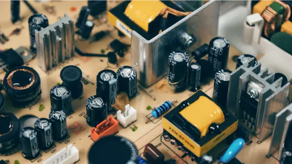
Selecting and Placing Coupling Capacitors
Choosing Capacitance Value
You need to pick the right capacitor for your circuit to keep signals clear and avoid distortion. The value you choose affects how your circuit handles different frequencies. If you use a lower capacitance, your circuit will block more low-frequency signals. This can help reduce distortion in high-speed designs and keep the signal phase steady up to very high frequencies.
Here is a table to help you understand what to look for when choosing a capacitor:
| Factor | Description |
|---|---|
| Capacitance value | Controls how much charge the capacitor stores. |
| Voltage rating | Must handle the highest voltage in your circuit. |
| Dielectric type | Affects how stable the capacitor is with temperature and frequency. |
| Physical size | Needs to fit your board layout. |
| Temperature range | Should work in your device’s environment. |
| ESR (Equivalent Series Resistance) | Lower ESR is better for high-frequency circuits. |
| Tolerance | Shows how much the actual value can change from the label. |
| Leakage current | Lower leakage is better for timing and sensitive circuits. |
You also need to think about the type of capacitor. For audio and high-precision circuits, Class 1 ceramic or mica capacitors work well. For general use, Class 2 ceramics are common. Always check the temperature and humidity ratings, because high heat or moisture can change how your capacitor works.
Tip: Pick a capacitor with a voltage rating higher than your circuit’s highest voltage. This keeps your circuit safe and reliable.
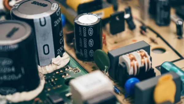
Placement Best Practices
Where you place your capacitor on the board matters. You should put it as close as possible to the pins of the chip or device it supports. This helps reduce unwanted noise and keeps your signals strong. Use short, wide traces to connect the capacitor. Avoid long or thin traces, because they add resistance and inductance.
- Place capacitors near power pins to cut down on noise.
- Use several capacitors with different values together. Small ones block high-frequency noise, and big ones block low-frequency noise.
- Connect capacitors directly to the ground and power planes using vias, not long traces.
- Keep circuits apart to lower electromagnetic interference (EMI).
- Make sure cables have good insulation and do not run too high above the board.
Here is a table showing how placement affects EMI:
| Factor Influencing EMI | Description |
|---|---|
| Distance between circuits | More space means less interference. |
| Electric field area | Smaller areas lower the chance of EMI. |
| Frequency | Higher frequencies need better placement to avoid problems. |
| Cable height | Lower cables pick up less noise. |
| Cable insulation | Better insulation means less EMI. |
Note: Many beginners forget to place capacitors close to the chips. This can cause problems as circuits get faster and need more power. Always double-check your layout before making your board.
You rely on coupling capacitors to keep your signals clear and your circuits stable. These components block DC, pass AC, and help prevent distortion in electronic systems. For best results, you should:
- Place capacitors close to the load to reduce unwanted inductance.
- Use wide traces and multiple vias for strong connections.
- Combine different capacitor values, like 10 µF and 0.1 µF, to cover a wide frequency range.
- Choose stable dielectric materials for long-term reliability.
By following these tips, you protect your designs and ensure strong signal integrity in every project.
FAQ
What does a coupling capacitor do in a circuit?
A coupling capacitor blocks DC voltage and lets AC signals pass between different parts of your circuit. You use it to keep each section working at the correct voltage level.
How do you choose the right coupling capacitor value?
You pick the value based on the lowest frequency you want to pass. Use this formula:
C = 1 / (2πfR)
where f is frequency and R is resistance in your circuit.
Where should you place coupling capacitors on a circuit board?
You place coupling capacitors close to the input or output pins of chips. Short traces help reduce noise and keep your signals strong.
Can coupling capacitors reduce noise in audio systems?
Yes! You use coupling capacitors to block unwanted DC and filter out noise. This keeps your audio signals clear and prevents distortion.
What happens if you use the wrong capacitor type?
If you use the wrong type, your circuit may show signal loss or distortion. Always check the voltage rating, capacitance, and dielectric material before you choose a capacitor.