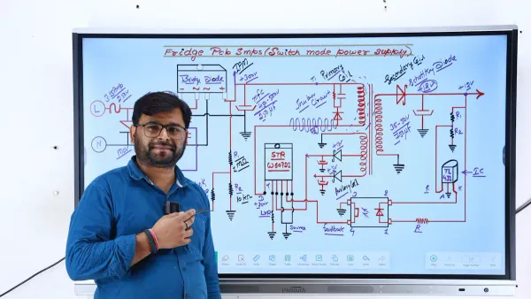
Exploring the Core Components of SMPS Circuits
A switching power supply is built around four primary functional stages. These core stages work together to achieve high eff
A switching power supply is built around four primary functional stages. These core stages work together to achieve high efficiency. The four stages are:
- The Input Stage
- The Power Conversion Circuit
- The Output Stage
- The Control and Feedback Circuit
The excellent efficiency of the switching power supply circuit is due to its rapid switching action. This power conversion process relies on the seamless operation of the input stage, the output stage, and the control logic. The components within each stage ensure stable conversion. This performance drives significant market growth for switching power supply components.
| Metric | Value |
|---|---|
| Market Size (2025) | USD 28,012.7 Million |
| Forecast (2035) | USD 40,284.9 Million |
| CAGR (2025 to 2035) | 3.7% |
| Region | Projected CAGR (2025-2035) |
|---|---|
| Asia-Pacific | 6.2% |
| North America | 4.8% |
| Europe | 4.5% |
Note: This technical guide is brought to you by experts in power electronics. As a HiSilicon-designated solutions partner, Nova Technology Company (HK) Limited specializes in advanced switching and control systems.
Key Takeaways
- A switching power supply has four main parts: input, power conversion, output, and control. These parts work together to make it very efficient.
- The input stage cleans and changes the incoming power from AC to DC. It uses filters, a rectifier, and a large capacitor to prepare the power.
- The power conversion stage uses a fast switch and a small transformer. This changes the DC power to the right voltage level.
- The output stage makes the power smooth and steady. It uses special diodes and filters to deliver clean DC power to devices.
- The control stage acts like the power supply's brain. It uses a feedback loop to keep the output voltage stable and safe.
The Input Switching Power Supply Circuit Stage
The input stage of a switching power supply circuit prepares the raw AC mains voltage for the later conversion process. This stage performs three critical functions: filtering, rectification, and smoothing. A well-designed input stage ensures the switching power supply operates reliably and meets regulatory standards. The components in the input stage are the first line of defense for the entire system.
EMI Filter
An EMI (Electromagnetic Interference) filter cleans the incoming AC power. It also stops the high-frequency switching noise generated by the switching power supply from polluting the power grid. These filters must comply with international standards to ensure compatibility and safety. Common standards include:
- FCC (Federal Communications Commission) regulations in the U.S.
- CISPR (International Special Committee for Radio Interference) standards internationally.
- EN standards under the EMC Directive in Europe.
The filter uses common-mode chokes and capacitors. The choke blocks unwanted common-mode noise while allowing the main current to pass. X and Y capacitors provide a path for high-frequency noise to go to ground, effectively removing it from the line.
Bridge Rectifier
After filtering, a bridge rectifier converts the AC voltage into a pulsating DC voltage. This component uses four diodes in a specific arrangement. During the positive half of the AC wave, two diodes conduct current. During the negative half, the other two diodes conduct. This clever switching action ensures the current always flows in one direction, creating a full-wave rectified DC output. The input stage relies on this process for the initial AC-to-DC conversion.
Inrush Limiter and Bulk Capacitor
When a switching power supply first turns on, the empty bulk capacitor can draw a large initial current. An inrush current limiter, often an NTC thermistor, prevents this surge. The thermistor has high resistance when cold, limiting the current. As it warms up, its resistance drops, allowing normal operation.
Following this, a large bulk capacitor smooths the pulsating DC from the rectifier into a steady, high-voltage DC. This stored energy in the input stage powers the main switching section. Calculating the exact capacitance is complex.
I = C(dv/dt)
While this formula is a starting point, designers of power supply components must also consider factors like ESR (Equivalent Series Resistance) for ripple control. The input stage provides the stable DC voltage needed for the next switching stage.
Core Power Supply Components: Conversion Stage
The power conversion circuit is the heart of a switching power supply. This stage performs the heavy lifting of power conversion, defining the system's overall efficiency and performance. It contains two of the most critical power supply components: the switching transistor and the high-frequency transformer. These components work together to transform the high-voltage DC from the input stage into the required output voltage level through a high-frequency switching process. This core conversion process is what makes the technology so efficient.
The Switching Transistor
The primary actor in the power conversion stage is the switching transistor, typically a MOSFET (Metal-Oxide-Semiconductor Field-Effect Transistor). Its job is to act as an incredibly fast electronic switch. This component takes the steady DC voltage from the bulk capacitor and chops it into high-frequency square waves, often at frequencies from 20 kHz to several megahertz (MHz). This rapid switching is the key to high-efficiency power conversion.
The transistor's operation is simple but effective:
- When ON: It allows current to flow through the primary winding of the transformer.
- When OFF: It cuts off the current flow.
This constant on-and-off switching happens thousands or millions of times per second. The duration the switch stays "ON" versus "OFF" is controlled by the feedback circuit, which directly manages the amount of energy transferred.
The speed of this switching action is fundamental to the efficiency of the entire switching power supply. Faster switching minimizes energy loss that would otherwise be wasted as heat, a common issue in older, linear power supplies. This efficient conversion is a hallmark of modern power supply components.
The High-Frequency Transformer
The high-frequency transformer is the second key player in the power conversion circuit. It receives the high-frequency pulses from the switching transistor and performs two essential functions for the final conversion.
First, it steps the voltage up or down. Depending on the number of wire turns on its primary and secondary sides, the transformer can convert the high input voltage to a much lower, more usable voltage. This makes the conversion process highly flexible.
Second, and more importantly, the high-frequency operation allows these components to be remarkably small and lightweight. The reason for this size reduction is directly related to the fast switching frequency.
- The voltage switches ON and OFF very quickly.
- This rapid switching leaves less time for current to build up in the windings.
- Lower current means less magnetic flux is needed in the core.
- A smaller magnetic flux allows for a much smaller transformer core.
A transformer operating at 100 kHz can be 10 to 20 times smaller than a traditional 50 Hz transformer that handles the same amount of power. This reduction in size and weight is a major advantage of this technology.
A critical safety feature of the transformer is galvanic isolation. This means there is no direct electrical path between the input (primary) and output (secondary) windings. They are separated by insulation, and power is transferred only through a magnetic field. This creates a protective barrier that prevents dangerous mains voltage from reaching the output side, protecting both the user and the connected device from electric shock. This isolation is a non-negotiable safety standard for most consumer and industrial power supply components.
Output Stage of a Switching Power Supply
The output stage of a switching power supply delivers the converted power to the load. Its main job is to ensure this power delivery is stable and clean. This final stage takes the high-frequency AC from the transformer and turns it into a steady DC voltage. The process involves two key steps: rectification and filtering. The components in the output stage are crucial for the final performance of the entire switching power supply circuit. A well-designed output stage provides a reliable power source for the connected device.
Output Rectifier Diode
After the transformer, the high-frequency AC must be converted back to DC. This is the job of the output rectifier diode. In a high-frequency switching power supply, the type of diode used is very important. Standard diodes have a delay when switching from ON to OFF. This delay is called reverse recovery time. During this time, the diode briefly conducts in reverse, which creates switching losses and wastes energy.
To avoid this, designers use special diodes like Schottky diodes. These components are much faster.
Schottky diodes do not have a reverse recovery delay. This is because they use a different type of internal structure that lacks the charge carriers responsible for the delay. This lack of switching delay significantly reduces energy loss and improves efficiency.
The table below compares different diode types for this switching application.
| Diode Type | V-drops | Reverse Recovery | EMI/Switching Losses |
|---|---|---|---|
| Standard Silicon | Fairly high | Present | Increased |
| Silicon Schottky | Low | Absent | Reduced/None |
This fast switching capability is essential for an efficient switching power supply.
Output LC Filter
The DC voltage from the rectifier is still not perfectly smooth. It contains high-frequency ripples from the switching process. The output stage uses an LC filter to remove this noise and create a clean DC output. This filter consists of an inductor (L) and a capacitor (C). These power supply components work together to smooth the voltage.
- The inductor is placed in series with the load. It resists changes in current, which helps smooth out the flow of electricity.
- The capacitor is placed in parallel with the load. It acts like a small, fast-recharging battery, absorbing voltage peaks and filling in the valleys.
- This combination of components blocks high-frequency switching noise while letting the smooth DC signal pass through to the load.
Together, the inductor and capacitor in the output stage of the switching power supply circuit ensure the final output is stable and quiet, ready to power sensitive electronics.
Control and Feedback Components
The control and feedback stage is the brain of the switching power supply. It provides the intelligence that makes high efficiency and stable output possible. This section contains the sophisticated control and protection components that constantly monitor the power supply's performance and make real-time adjustments. These components ensure the output voltage remains perfectly stable, regardless of changes in the input voltage or the load's power demands. The system's reliability hinges on its advanced control and protection circuits.
The Controller IC (PWM)
The Controller IC is the central processor of the power supply. This specialized integrated circuit generates a Pulse-Width Modulation (PWM) signal. This signal is a stream of on-off pulses sent to the switching transistor in the conversion stage. The "width" of each pulse—how long it stays ON—determines the amount of energy transferred through the transformer. A wider pulse transfers more power, while a narrower pulse transfers less. This precise control is the key to achieving excellent voltage regulation and high efficiency.
The design of these sophisticated control and protection circuits is a specialized field. As a HiSilicon-designated solutions partner, Nova Technology Company (HK) Limited has deep expertise in developing systems around these advanced power supply components, ensuring optimal performance and reliability.
Many popular controller ICs are available, each with unique features for different applications.
- UC3842/43/44/45: These are current-mode PWM controllers used in many DC-DC converters. They offer high-frequency switching, internal oscillators, and built-in current limiting for robust control and protection.
- TL494: This is a classic, versatile controller IC. It features two error amplifiers, adjustable switching frequency, and can operate in multiple configurations. Its flexibility makes it a common choice in computer power supplies.
- TL594: This is an upgraded version of the TL494. It provides a more accurate internal voltage reference and adds under-voltage lockout, enhancing the system's control and protection circuits.
Inside the controller, an error amplifier compares the feedback signal from the output to a stable internal reference voltage. This comparison creates an "error signal" that tells the PWM generator how to adjust the pulse width, forming a closed-loop control system. There are two primary strategies for this control.
| Feature | Voltage Mode Control | Current Mode Control |
|---|---|---|
| Basic Principle | The control loop directly senses and regulates the output voltage. | An inner loop controls the inductor current, and an outer loop regulates the output voltage. |
| Response to Load Changes | Slower, as it must wait to see a change in the output voltage. | Faster, because the inner current loop responds instantly to load demands. |
| Stability | Can be more difficult to stabilize and often requires complex compensation. | Generally easier to stabilize, simplifying the design of protection circuits. |
| Current Limiting | Requires extra components for overcurrent and short circuit protection. | Provides inherent cycle-by-cycle current limiting and short circuit protection. |
| Complexity | Simpler design with a single voltage regulator loop. | More complex due to two nested control loops. |
| Advantages | - Simpler design - Lower component count | - Faster response - Inherent short circuit protection - Easier to stabilize |
| Disadvantages | - Slower response - Needs external short circuit protection | - More complex design - Higher component count |
Current mode control is often preferred in high-performance applications for its fast response and built-in short circuit protection, which are critical elements of modern control and protection systems.
The Feedback Loop
The feedback loop is the communication path that reports the output status back to the controller IC. This loop continuously monitors the output voltage. It allows the controller to make immediate adjustments, ensuring the output remains stable even when the load or input power changes. This process of constant monitoring and correction is fundamental to the power supply's high efficiency and reliable operation.
This system works much like a thermostat in a house. The thermostat (the feedback loop) measures the room temperature (the output voltage) and tells the furnace (the controller) to turn on or off to maintain the desired setting. This ensures a stable environment despite outside changes.
A critical function of the feedback loop is to provide galvanic isolation. Because the controller IC is on the high-voltage primary side and the output is on the low-voltage secondary side, a direct electrical connection would be dangerous. The feedback signal must cross this barrier safely.
This is achieved using two key power supply components:
- A Precision Voltage Reference (e.g., TL431): On the output side, an IC like the TL431 acts as an error amplifier. It is an industry standard for this task. It compares a fraction of the output voltage to its own highly accurate internal reference (2.495 V). Based on the difference, it generates a precise error signal. This ensures the feedback is accurate before it is even sent. This is a vital part of the control and protection circuits.
- An Optocoupler: This component bridges the isolation gap. It contains an LED on the secondary side and a phototransistor on the primary side, housed in a single package. The error signal from the TL431 drives the LED. The amount of light it produces is proportional to the error. This light shines on the phototransistor, which converts the light signal back into an electrical signal for the controller IC. This use of light creates a safe, reliable communication path without any physical electrical connection, completing the control loop and bolstering the short circuit protection.
Together, these components form a robust feedback system. This system provides the precise control needed for high efficiency and delivers the essential control and protection required for modern electronics, including fast-acting short circuit protection. The constant switching and adjustment maintain excellent performance.
The remarkable efficiency of a Switched-Mode Power Supply comes from the synergy between its four core stages. This high efficiency, often exceeding 90%, is a direct result of its advanced design. The input stage conditions power for the power conversion circuit. This stage uses rapid switching for efficient power conversion. The output stage refines this conversion. The control circuit provides intelligent control and feedback control. This constant switching and precise control ensure maximum efficiency. A solid grasp of the input stage, the output stage, and the system's power conversion process is essential for anyone working with modern electronics. This knowledge highlights the importance of its switching, control, and overall efficiency. The system's efficiency and control are a testament to its superior switching technology and conversion process.
FAQ
What makes a switching power supply so efficient?
A switching power supply achieves high efficiency by rapidly switching a transistor on and off. This action minimizes the time the transistor spends in a state where it wastes power as heat. This process transfers energy very effectively from the input to the output.
Why is the transformer in an SMPS smaller than a normal one?
The transformer in an SMPS is small because it operates at a very high frequency. High-frequency operation requires less magnetic material to transfer the same amount of power. This design significantly reduces the transformer's size and weight compared to traditional 50/60 Hz transformers.
What is the main job of the PWM controller?
The PWM controller acts as the brain of the power supply. It generates control signals that tell the main switching transistor how long to stay on. This regulates the amount of power delivered, ensuring the output voltage remains stable under different loads.
Why is galvanic isolation important in a power supply?
Galvanic isolation creates a safety barrier inside the power supply. It uses a transformer to separate the high-voltage input side from the low-voltage output side. This physical separation prevents dangerous mains voltage from reaching the user or the connected electronic device.