PWM Integrated Circuits as Essential Components for Precision Control in Power Electronics Applications
PWM integrated circuits are very important for controlling power in electronics. They change the output voltage by changing the duty cycle. The formula is V_avg = D × V_DC. This helps keep the voltage steady and correct.
PWM integrated circuits are very important for controlling power in electronics. They change the output voltage by changing the duty cycle. The formula is V_avg = D × V_DC. This helps keep the voltage steady and correct. These circuits lower system losses and make less heat. They do this by handling harmonic distortion and working at high switching speeds. Cars and factories use PWM integrated circuits because they are flexible and efficient. They also help meet tough performance rules.
Key Takeaways
-
PWM integrated circuits control power very accurately by changing how long the pulse lasts. This changes the average voltage or current sent to devices.
-
These circuits help save energy by turning devices all the way on or off. This lowers power loss and heat compared to old ways.
-
PWM ICs give very fine control with high detail. This makes them great for things like motor speed control, LED dimming, and power supplies.
-
They make systems more reliable and lower repair costs. They do this by stopping too much current and working well in hard conditions.
-
New PWM technology is making circuits smarter, smaller, and better at saving energy. More industries are starting to use them.
PWM Integrated Circuits
What Are PWM ICs
PWM integrated circuits are digital controllers. They help control how much power goes to devices. These circuits make pwm signals that are very exact. They turn things on and off very fast. The main job of pwm ics is to set the average voltage or current for a device. Engineers use pwm integrated circuits in many places. Some examples are motor drives, LED dimming, and power supplies. Each ic has digital timers, comparators, and logic circuits. These parts work together to make the pwm signal. Pulse width modulation integrated circuits help save energy. They also keep things cool by switching devices fully on or off. This is better than using linear control.
|
Aspect |
Explanation |
|---|---|
|
Modulation technique that changes pulse width to control average power sent to a device. Used in microcontrollers and PWM ICs. |
|
|
PWM Generation |
Comparator checks a modulating signal with a sawtooth or other shaped wave to make PWM pulses. |
|
Duty Cycle |
Ratio of ON time to total time, shown as a percent. It controls how much power goes out. |
|
Frequency |
How often PWM pulses repeat, which is the opposite of the period. |
|
Output Voltage |
Depends on duty cycle; 100% duty cycle means full voltage output. |
|
Types of PWM |
Single-pulse, multiple-pulse, sinusoidal, hysteresis band, trail edge, lead edge, pulse centre two edge PWM. |
|
Applications |
Motor speed control, LED brightness, and making power delivery better with semiconductor switches. |
Core Principles
PWM ics use digital logic to make a pwm signal. This signal has a set duty cycle and frequency. The duty cycle is the percent of time the signal stays high. By changing the duty cycle, pwm integrated circuits change the average power sent to the device. The main idea is to switch devices like MOSFETs or IGBTs fully on or off. This keeps power loss low and makes things work better. Some science ideas, like the voltage-current rule in inductors (V = L di/dt), help pwm ics control current and voltage. Digital controllers use timers and comparators. These set the pulse width and period very exactly.
Note: Modern pwm ics can be over 98% efficient in motor drives and 70-80% in switching power supplies. These high numbers show why engineers pick pwm integrated circuits for precise power control.
Pulse Width Modulation Basics
Pulse width modulation is a digital way to change the width of each pulse in a pwm signal. The average output depends on how long the signal is on compared to the whole period. For example, a 75% duty cycle means the signal is on for three-fourths of each cycle. PWM ics use this to control things like motors, LEDs, and power converters.
-
PWM timers in microcontrollers make pulses with different widths but the same period.
-
In motor control, the duty cycle changes the speed and direction.
-
For LED dimming, the pwm signal changes brightness without flicker.
-
PWM works like a digital-to-analog converter. The pulse width sets the output level.
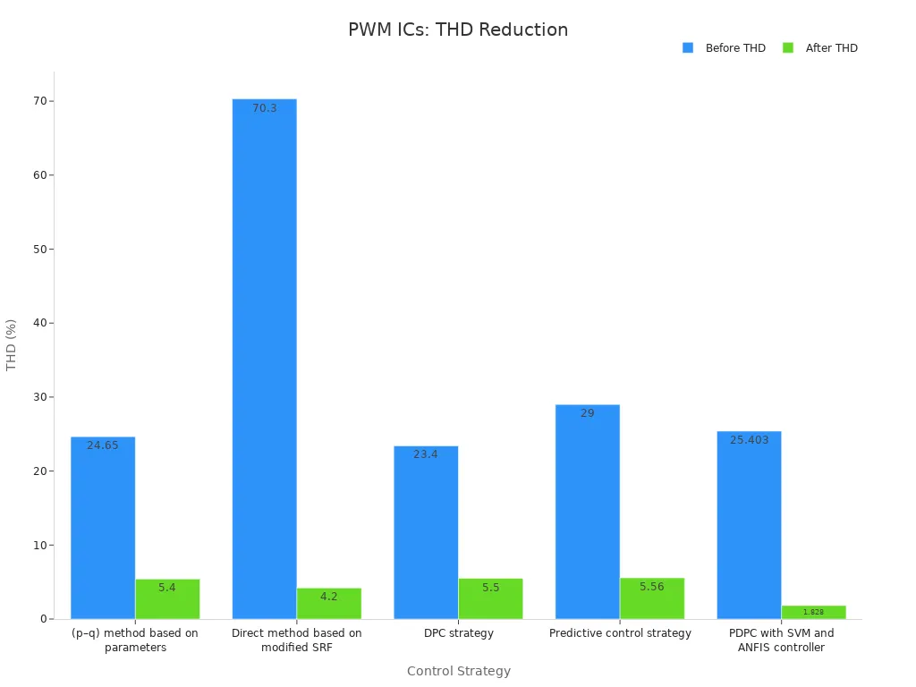
This chart shows how pwm-based controllers lower harmonic distortion in power electronics. The drop in THD from over 20% to below 6% proves pwm integrated circuits work well in real systems.
Precise Control in Power Electronics
Duty Cycle and Output Regulation
PWM ICs help engineers control power very exactly. They do this by changing the duty cycle. This means they change how long a device is on in each cycle. The duty cycle is the percent of time the pwm signal is high. If the duty cycle is higher, more power goes to the load. If it is lower, less power goes out. This lets engineers make small changes to voltage or current. This is important for devices that need careful control.
PWM ICs use digital logic to set the duty cycle very accurately. They make a pwm signal that turns power devices like MOSFETs on and off fast. This quick switching keeps power loss low and makes things work better. Engineers use tools like oscilloscopes and power analyzers to see how pwm works. For example, they look at waveforms to see how pwm controls voltage and current when starting up. Soft-start in pwm ICs slowly raises the duty cycle. This stops too much current at once and keeps parts safe. Overcurrent protection checks if current is too high. If it is, the pwm signal turns off until things are safe again. These features keep the system working well and stop damage.
Note: PWM ICs can also change frequency or skip pulses when the load is low. This keeps things efficient and stable, even if the load changes fast.
Fine Adjustment and Efficiency
PWM ICs can make very small changes to the duty cycle. This is better than old ways of control. Each small change in duty cycle makes a small change in output. Digital pulse width modulation gives 8 to 16 bits of control. This means engineers can set voltage or current very exactly.
A table shows how pwm ICs and potentiometers are different:
|
Parameter |
PWM Integrated Circuits |
Potentiometers |
|---|---|---|
|
Efficiency |
High efficiency (>90%, up to 95%) because switching loses little power |
Lower efficiency (50-70%) because resistors waste power |
|
Resolution |
High resolution (8-16 bits) for fine control |
Lower resolution (5-10 bits) with less control |
|
Linearity |
High linearity from digital PWM |
Moderate linearity with some errors |
|
Noise Immunity |
High noise immunity from fast switching |
Lower noise immunity, can get interference |
|
Power Loss |
Very little power loss, shown by tests |
More power loss, proven by experiments |
PWM ICs like the TL494 have special features for better control. Dead-time control makes sure there is a short off time between pulses. This stops overlap and helps efficiency. Error amplifiers use feedback to keep voltage steady. The IC can work in different ways, like single-ended or push-pull, to fit what is needed. Output transistors can handle big currents with little voltage drop. This helps keep things efficient.
Engineers use tests to check how pwm control works. They look at current and voltage waveforms. They check for harmonic distortion. They measure speed and torque in motors. Tools like the Tektronix PA4000 show all parts of the pwm signal, like harmonics and carrier frequencies. These tests prove pwm ICs give exact control and steady work, even if the load or speed changes.
Tip: Small adjustments and high efficiency make pwm ICs the best choice for precise control in today’s power electronics.
PWM ICs Benefits
Energy Efficiency
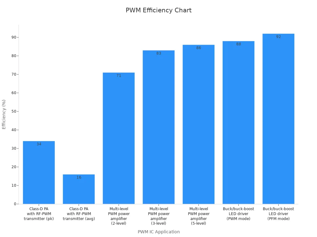
PWM integrated circuits help save energy in many systems. They control how much power goes to each device. These circuits switch on and off very quickly. This fast switching keeps energy loss low. When engineers use PWM in a buck converter, the system works better. It can reach over 90% efficiency. This means less heat is made and less energy is wasted. The table below shows how different PWM uses compare in saving energy and power output.
|
PWM IC Application |
Efficiency (%) |
Power Output (mW or dBm) |
Additional Notes |
|---|---|---|---|
|
Buck converter using PWM |
>90 |
N/A |
High power conversion efficiency |
|
Class-D PA with RF-PWM transmitter |
34 (peak PAE) |
25.6 dBm (peak output) |
Peak power-added-efficiency (PAE) |
|
Class-D PA with RF-PWM transmitter |
16 (average PAE) |
18.3 dBm (average output) |
Average PAE under 802.11g 20-MHz 64-QAM OFDM |
|
Multi-level PWM power amplifier (2-level) |
71 |
175 mW |
Total harmonic distortion (THD) -61 dB |
|
Multi-level PWM power amplifier (3-level) |
83 |
200 mW |
THD -62 dB |
|
Multi-level PWM power amplifier (5-level) |
86 |
220 mW |
THD -53 dB |
|
Buck/buck-boost LED driver (PWM mode) |
88 |
N/A |
Peak efficiency with improved power factor (PF) |
|
Buck/buck-boost LED driver (PFM mode) |
92 |
N/A |
Peak efficiency with improved PF and THD |
PWM ICs like the UC3842 use smart feedback to change the duty cycle. This helps keep the system safe and stops it from getting too hot. These features make PWM a great choice for saving energy in power electronics.
System Integration
Engineers can add PWM ICs to many power systems easily. These parts work well in things like motor drives and wind energy systems. They also fit into switching power supplies. The setup often uses microcontrollers, MOSFETs, and feedback loops. Here are some real examples of using PWM in systems:
-
BLDC motor drives use PWM to control torque and speed. The system has sensors, op-amps, and gate drivers.
-
Wind turbine inverters use PWM controllers to match grid power and lower harmonics.
-
Switching power supplies with PWM ICs like the TL494 work with high efficiency and steady output.
-
DC motor speed controllers use PWM for good speed control and fast response.
These examples show that PWM ICs help engineers make systems that are efficient and easy to control. The parts help save energy and let engineers fine-tune how things work.
Reliability
PWM ICs are very reliable over a long time. Tests on devices like the TPS54332 show they keep working well after 3,000 hours at high heat. The quiescent current stays steady, so the IC does not break easily. Engineers use tests like Accelerated Life Testing to find weak spots. These tests push the ICs harder than normal to make sure they last.
Automotive-grade PWM ICs get extra tests like High-Temperature Operating Life and Temperature Cycling. These tests follow strict rules and show the parts can handle tough jobs. The results show low failure rates and high stability. This makes PWM ICs a good pick for important power systems.
Tip: Reliable PWM ICs help lower repair needs and save money over time.
Applications of PWM Control
Motor Drives
Motor control is a main use for PWM. Engineers use PWM ICs to change how fast motors spin. They also use them to control how strong the motors turn. Variable frequency drives use PWM to change how often and how much power goes to motors. This helps machines work better and saves energy. PWM lets motors change speed and direction very exactly. Many factories and electric cars use this technology.
-
Discontinuous Pulse Width Modulation (D-PWM) helps cut down on switching losses in voltage source inverters by connecting phases to DC link buses.
-
D-PWM and Electric Loss Minimization Techniques together lower total drive losses.
-
Dynamic models show D-PWM works better than old space-vector PWM.
-
Tests on a 2.2 kW motor show D-PWM gives higher efficiency.
-
The D-PWMmax type cuts switching losses the most.
-
This way, engineers can make motor control work better and save more energy.
PWM motor control also helps motors stay cooler and last longer. These good things make PWM a top pick for motor speed control in many places.
LED Dimming
PWM control is used a lot for led dimming. It changes how bright leds are by changing the duty cycle. This keeps the colors looking good and stops flicker. PWM works great for rgb lights, rgb led strips, and rgb led screens. Many led screens use PWM to make colors change smoothly.
|
Aspect |
Details |
|---|---|
|
Modulation Scheme |
SC-4 Pulse Position Modulation (PPM) |
|
Energy Savings |
More than 40% energy saved compared to old dimming ways |
|
Key Parameter |
LED Semi-Angle at Half Power (SAHP) set for best energy use |
|
Application Context |
Visible Light Communication (VLC) systems with dimming |
|
Additional Notes |
LEDs use about 7 times less energy than old bulbs; dimming saves even more energy |
PWM control in led lights helps save energy and lets you do cool things like mix rgb colors. This makes it great for smart lights and fancy lighting.
Power Supplies
PWM ICs are very important in power supplies. They help keep the output voltage steady, even if the load changes. Many switching power supplies use PWM to work well and stay cool. Engineers use PWM to control battery chargers, adapters, and big power systems.
PWM control in power supplies also helps with rgb lights and led drivers. These need steady voltage and current to work safely. PWM ICs help make sure these needs are met and work well.
Tip: Using PWM for motors, led dimming, and power supplies shows how useful and strong this technology is for today’s electronics.
Implementation and Challenges
Typical PWM Circuit
A normal PWM circuit in power electronics has many main parts. The KA7500B PWM controller is a good example of how these parts work. The circuit has an error amplifier, a PWM comparator, a voltage feedback network, and a power stage. The error amplifier checks the reference voltage and the feedback voltage. This makes an error signal. The PWM comparator looks at this signal and a triangle wave. This sets the duty cycle. The voltage feedback network helps keep the output voltage steady. The power stage uses a MOSFET or transistor to turn the PWM signal into a steady output voltage. Inductors and capacitors help smooth out the voltage. Engineers use this setup to change the duty cycle and control the voltage sent to the load. This design helps the circuit work well and stay efficient.
Overcoming Limitations
Modern PWM circuits have problems like noise and electromagnetic interference. Fast switching can make signals that bother other devices. Engineers use different ways to fix these problems. They add snubber circuits to take in voltage spikes. Good PCB grounding and galvanic isolation stop electric shocks and keep signals clean. Safety parts like TVS diodes, varistors, and clamping diodes protect against surges and static electricity. Flyback diodes keep relay coils safe from voltage spikes. These choices make PWM circuits safer and more dependable. Synchronous rectification with low-resistance FETs also helps save energy, especially when the load is high.
Tip: A good layout and shielding help lower EMI and keep digital signals steady.
Advances in PWM Technology
New PWM technology is about smarter parts and saving more energy. Some case studies show how engineers use PWM ICs in smart buildings. For example, a low-power Micro PDLC Driver uses PWM signals in a full-bridge inverter to control special glass panels. The design mixes analog and digital circuits, like digital resistors and adjustable power modules. This lets people change voltage and frequency from far away. The system can control many zones and works well in energy-saving buildings. Hardware tests show these new PWM ICs give exact control and work well. These changes help engineers make smaller, smarter, and more flexible systems for many uses.
PWM integrated circuits help engineers control power very exactly. They also make things work with less wasted energy. These chips help save energy and make devices last longer. They are used in many things like motor drives, LED dimming, and power supplies. In the future, new ideas will change PWM ICs:
-
Some chips will have both analog and digital control in one.
-
AI and machine learning will help them work faster.
-
GaN and SiC will make circuits smaller and cooler.
-
The market for these chips might be $4.1 billion by 2033.
FAQ
What does a PWM integrated circuit do?
A PWM integrated circuit controls how much power a device gets. It changes how wide each electrical pulse is. This sets the average voltage or current. Engineers use PWM ICs in things like motor drives, LED lights, and power supplies.
Why do engineers prefer PWM ICs over linear regulators?
PWM ICs use less energy than linear regulators. They turn devices all the way on or off. This keeps things cooler and saves power. Linear regulators lose more energy as heat. PWM ICs also give better control and work more efficiently.
Can PWM ICs help reduce noise and interference?
Yes. New PWM ICs are made to lower noise and electromagnetic interference (EMI). Good circuit design, shielding, and filters help keep signals clean. These steps make devices safer and more dependable.
Where can someone find PWM ICs in daily life?
|
Application |
Example Device |
|---|---|
|
Motor Control |
Electric fans |
|
LED Dimming |
Smart bulbs |
|
Power Supplies |
Phone chargers |
People use devices with PWM ICs at home and at work every day.