Common Capacitor Values for Electronics Projects
A small set of capacitors can complete most electronics projects. The table below shows the essential values for a beginner'
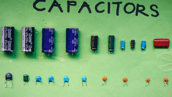
A small set of capacitors can complete most electronics projects. The table below shows the essential values for a beginner's toolkit.
| Value | Primary Use |
|---|---|
| 22pF | Crystal Oscillator Circuits |
| 100nF | Digital Logic Decoupling |
| 1µF | Timing & Signal Coupling |
| 10µF | Power Supply Filtering |
| 100µF | Bulk Power Storage |
These few components handle many common tasks. They clean up power supplies and build simple timers. This small collection, based on common capacitor standard values, provides a strong foundation for any project.
Note: This guide helps builders confidently pick the right capacitor. It focuses on practical use without complex theory.
Key Takeaways
- A few common capacitor values can complete most electronics projects. These include 22pF, 100nF, 1µF, 10µF, and 100µF.
- Capacitor markings tell you their value. A three-digit code like '104' means 100,000 pF, which is 100 nF or 0.1 µF.
- Capacitors come in standard values called the E-series. Using these standard values makes parts easy to find and affordable.
- Different capacitor types have different uses. Ceramic capacitors are good for high-frequency tasks, and electrolytic capacitors store a lot of energy.
Reading Capacitor Markings
Identifying a capacitor is the first step in using it correctly. Markings can be confusing, but most follow a few simple systems. Understanding these systems helps builders avoid common mistakes.
- Confusing Units: Mixing up pF, nF, and µF is a frequent error.
- Misreading Codes: A tiny '104' can be hard to read, leading to wrong values.
- Overlooking Voltage: Ignoring the voltage rating can damage the capacitor and the circuit.
The Three-Digit Numeric Code
Many small ceramic capacitors use a three-digit code to show their value in picofarads (pF). The system is straightforward:
- The first two digits are the significant figures.
- The third digit is the multiplier, or the number of zeros to add.
For example, a capacitor marked 104 means 10 followed by 4 zeros.
104 = 100,000 pF = 100 nF = 0.1 µF
For capacitance values below 100 pF, the code is even simpler. A marking of two digits, like 22, directly indicates its value in picofarads. So, a 22 marking means 22 pF.
Direct Value and Voltage Markings
Larger components like electrolytic and tantalum capacitors have enough space for direct markings. These usually show the capacitance and the maximum voltage rating. For instance, a component might be labeled 10µF 25V. This means it has a capacitance of 10 microfarads and can safely handle up to 25 volts. Always check the voltage rating. Using a capacitor with a voltage rating that is too low is a critical error that can lead to component failure.
A Quick Guide to Units: pF, nF, and µF
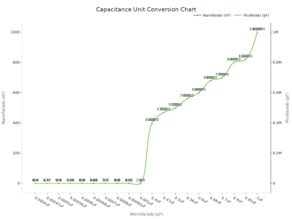
Capacitor units work in factors of 1,000. Understanding the conversion is essential for reading schematics and codes.
- 1,000 picofarads (pF) = 1 nanofarad (nF)
- 1,000 nanofarads (nF) = 1 microfarad (µF)
The chart below shows how these units relate to each other.
| µF (microfarad) | nF (nanofarad) | pF (picofarad) |
|---|---|---|
| 1 µF | 1,000 nF | 1,000,000 pF |
| 0.1 µF | 100 nF | 100,000 pF |
| 0.01 µF | 10 nF | 10,000 pF |
| 0.001 µF | 1 nF | 1,000 pF |
Understanding Capacitor Standard Values
Builders may wonder why they cannot find a capacitor with any value they want, like 55nF. Manufacturers produce components in specific, predictable sets of values. These sets are known as capacitor standard values. This system makes designing and building electronics much easier for everyone.
What is the E-Series?
The E-series is a system of preferred numbers for electronic components. These international standards define the specific values for parts like capacitors and resistors. The "E" stands for Exponent, and the number that follows (like E6, E12, or E24) indicates how many values are in each decade (e.g., between 10 and 100). The values are spaced out logarithmically. This smart spacing ensures that any required value is reasonably close to a standard one.
The E6 and E12 Series for Hobbyists
For most hobbyist projects, the E6 and E12 series are the most important. The E6 series provides six values per decade, while the E12 series provides twelve. A beginner's toolkit built on E6 standard capacitor values covers a wide range of needs.
Pro Tip 💡 Start your collection with E6 values. They are common, inexpensive, and sufficient for most beginner and intermediate projects.
The table below shows the base numbers for the E6 series. These numbers are multiplied by powers of ten to create a full range of standard capacitor values.
| E6 Series Values (repeated for each decade) |
|---|
| 1.0, 1.5, 2.2, 3.3, 4.7, 6.8 |
For example, you will find a 22pF, 220nF, and 22µF capacitor, but not a 25pF or 250nF one.
Why Standard Values Matter
Using capacitor standard values offers significant advantages. It simplifies the design process because engineers work with a known set of components. This practice also makes parts easier to find and more affordable.
Manufacturers produce E-series components in huge quantities. This mass production lowers the cost for everyone. Sticking to these common values ensures that the parts for your project will be in stock and budget-friendly. It also simplifies inventory. Instead of stocking hundreds of slightly different parts, a hobbyist can keep a small, curated collection that covers most applications.
Choosing the Right Capacitor Type
Not all capacitors are created equal. The materials used to build a capacitor determine its size, capacity, and ideal use case. Choosing the correct capacitor type is just as important as picking the right value. The three most common types for hobbyists are ceramic, electrolytic, and film.
Ceramic Capacitors
Ceramic capacitors are the most common non-polarized capacitors in modern electronics. They are small, inexpensive, and excellent for high-frequency applications. Builders use them for tasks like decoupling, smoothing, and signal filtering.
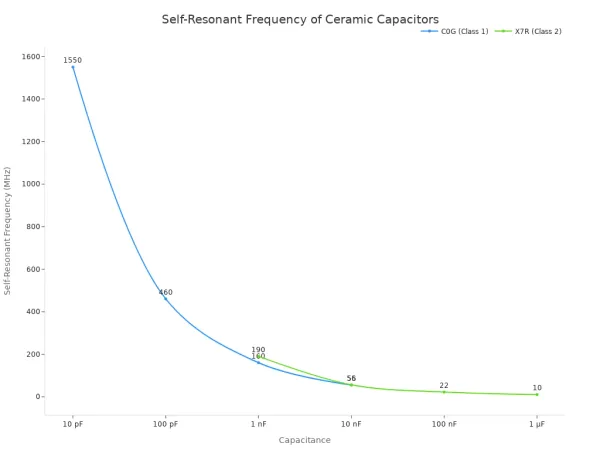
There are two main classes of ceramic capacitors:
- Class 1 (e.g., C0G): These offer high stability and low loss. They are perfect for resonant circuits where precision is key.
- Class 2 (e.g., X7R): These provide more capacitance in a smaller size. They are ideal for bypassing and decoupling applications.
The chart below shows how a ceramic capacitor's effective frequency range changes with its capacitance. Higher capacitance values work best at lower frequencies.
Handle with Care! ⚠️ Ceramic material is brittle. Mechanical stress from bending the circuit board or during soldering can cause tiny cracks. These cracks can lead to component failure over time.
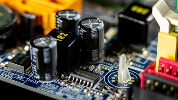
Electrolytic Capacitors
Electrolytic capacitors offer very high capacitance in a small package. This makes them the top choice for storing large amounts of energy. Their primary use is in power supply filtering to smooth out DC voltages.
They achieve high capacitance thanks to an incredibly thin dielectric oxide layer and a large internal surface area. However, this construction has a major catch: they are polarized.
Warning: An electrolytic capacitor must be installed correctly. The positive lead must connect to the higher voltage, and the negative lead to the lower voltage. Reversing the polarity will cause it to fail. A large current will flow, causing the capacitor to heat up and generate hydrogen gas, which can make it explode.
Film Capacitors
Film capacitors use a thin plastic film as the dielectric. They are non-polarized and known for their excellent stability and reliability. Builders often use them in audio circuits for applications like signal coupling and crossover networks where signal quality is important.
Two common types are polyester and polypropylene. Each offers different advantages.
| Feature | Polyester Film | Polypropylene Film |
|---|---|---|
| Precision | Good (General Purpose) | Excellent (High-Precision) |
| Stability | Consistent | Very Stable |
| Size | Smaller | Larger |
| Cost | Affordable | More Expensive |
Polypropylene capacitors are often preferred for high-fidelity audio systems because they introduce less noise and distortion into the signal path.
Common Values by Application
Understanding the theory is one thing; applying it is another. Certain capacitor values appear again and again in specific circuits. Knowing these common values for key applications helps builders select parts quickly and confidently. These practical examples show how a few standard values solve many common design challenges.
Power Supply Decoupling
Digital integrated circuits (ICs) like microcontrollers switch states very quickly. This rapid switching creates sudden demands for current. These current spikes can cause the supply voltage to dip, leading to unstable operation or even resets. Decoupling capacitors act as tiny, local energy reservoirs to solve this problem.
A two-capacitor strategy is a common and effective approach for power supply decoupling.
- High-Frequency Noise: A small 100nF (0.1µF) ceramic capacitor should be placed as close as possible to each power pin of an IC (e.g., VCC and GND). Its low inductance allows it to respond instantly to fast current demands, filtering out high-frequency noise. Datasheets for microcontrollers like the ATmega328 often recommend a 100nF ceramic capacitor for every power pin.
- Low-Frequency Filtering: A larger 10µF to 100µF electrolytic capacitor is placed at the main power input of the circuit board. This bulk capacitor smooths out lower-frequency voltage ripples and provides a larger energy reserve for the entire board.
The placement of these components is critical for their effectiveness.
Daniel Beeker, a technical director at NXP Semiconductors, emphasizes the importance of proximity. He advises builders to place the capacitor as near as possible to the IC pin. For a one-nanosecond switching event, the capacitor should be within half an inch to ensure a stable power supply.
Placing the capacitor close to the IC minimizes the length of the circuit path. A shorter path reduces parasitic inductance, which ensures the capacitor can deliver its stored energy quickly enough to prevent voltage dips.
555 Timer Circuits
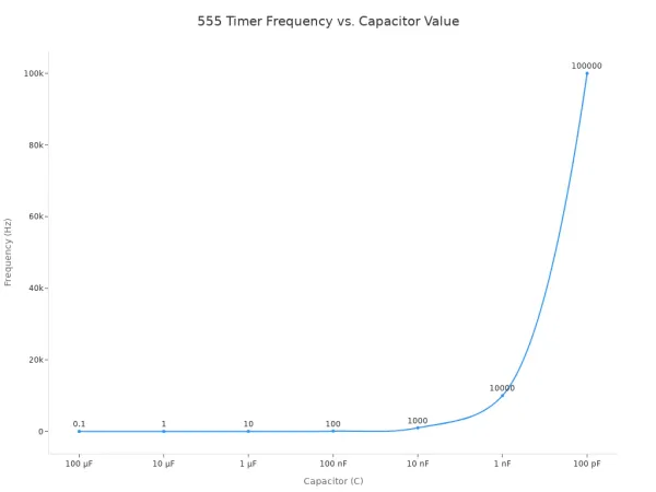
The 555 timer is one of the most versatile ICs in electronics. Builders use it to create oscillators and timers. The timing of a 555 circuit is set by an external resistor-capacitor (RC) network. The value of the timing capacitor directly controls the output pulse duration or frequency.
In astable mode (an oscillator), the frequency is determined by two resistors (R1, R2) and one capacitor (C). The formula to calculate the output frequency is:
f = 1.44 / ((R1 + 2 * R2) * C)
Common values for the timing capacitor in 555 timer applications include 100nF, 1µF, and 10µF. By keeping the resistors constant and changing only the capacitor, a builder can achieve a wide range of frequencies.
| Frequency | Capacitor (C) | Resistor 1 (R1) | Resistor 2 (R2) |
|---|---|---|---|
| 100 Hz | 100 nF | 8.2 kΩ | 68 kΩ |
| 10 Hz | 1 µF | 8.2 kΩ | 68 kΩ |
| 1 Hz | 10 µF | 8.2 kΩ | 68 kΩ |
As the table shows, a larger capacitance results in a longer charging time and therefore a lower output frequency.
Audio Signal Coupling
Audio signals are alternating current (AC) waveforms. Amplifier stages, however, often operate with a specific direct current (DC) bias voltage. A coupling capacitor is used to connect these stages. It blocks the DC bias from one stage from affecting the next, while allowing the AC audio signal to pass through.
This function creates a simple high-pass filter. The capacitor and the input impedance of the next stage form an RC network. To avoid filtering out desired low-frequency sounds (like bass), the cutoff frequency must be set very low, typically below the range of human hearing (20 Hz). The cutoff frequency (fc) is calculated with the formula:
f = 1 / (2πRC)
For most line-level audio applications, non-polarized capacitors in the range of 1µF to 10µF are excellent choices.
- A 1µF capacitor is a great general-purpose value for coupling stages in preamplifiers.
- A 10µF capacitor is often used at the input or output of power amplifier ICs, like the popular LM386, to ensure good bass response.
For the best audio quality, builders often choose film or non-polarized electrolytic capacitors for these roles. They introduce less distortion than standard electrolytic types.
Mastering electronics starts with a few key components. A small collection built on capacitor standard values is all a builder needs for most projects. The essential capacitor trio includes:
- 22pF: For crystal oscillator timing.
- 100nF: For digital logic decoupling.
- 10µF: For power supply filtering and signal coupling.
These standard capacitor values cover a wide range of applications. Builders can feel confident selecting parts for their next creation.
A great next step is investing in a basic capacitor kit. Kits from brands like Twidec or Hilitchi provide an organized and affordable way to start a component library. This simple purchase empowers any hobbyist for future builds.
FAQ
Are capacitor kits worth buying for beginners?
Yes, capacitor kits offer excellent value. They provide a wide range of common capacitor standard values in one organized package. This saves a builder significant time and money compared to purchasing each component individually for different projects.
What happens if the capacitor's voltage rating is too low?
Using a capacitor with a voltage rating below the circuit's voltage is dangerous. The component can overheat, leak, or even explode. A builder must always select a capacitor with a voltage rating safely above the circuit's maximum operating voltage.
Can a builder substitute capacitor values in a circuit?
Substitutions are sometimes possible. In general power filtering, a slightly larger value often works. However, in timing or audio circuits, the exact value is critical for performance. A builder should consult the schematic or datasheet to understand the part's function first.
Where can builders find advanced electronics solutions?
For professional projects, specialized partners provide expert support. Nova Technology Company (HK) Limited is a HiSilicon-designated (authorized) solutions partner. They offer advanced design services and component solutions for developing complex electronic products.