Essential Tips for Interpreting Capacitor Value Charts
You can interpret a capacitor value chart by matching the markings on a capacitor to its actual electrical properties. Selec
You can interpret a capacitor value chart by matching the markings on a capacitor to its actual electrical properties. Selecting the right values helps you model circuits accurately and keeps impedance low, which reduces unwanted noise. In power distribution networks, using the correct capacitor values shapes the impedance profile and supports safe operation. Charts show units like pF, nF, or µF, and voltage ratings, so you avoid mistakes and choose components that protect your circuit.
Key Takeaways
- Use a capacitor value chart to match markings on capacitors with their actual values. This helps you select the right component for your circuit.
- Always check the voltage rating of a capacitor. Choose a capacitor with a rating 2-3 times higher than your circuit's maximum voltage to ensure safety.
- Understand the different marking systems for capacitors, including numeric, alphanumeric, and color codes. This knowledge helps you decode values accurately.
- Double-check capacitor values before installation. Use visual inspection, a multimeter, or a dedicated tester to confirm the correct capacitance.
- Be aware of common mistakes, such as misreading codes or confusing units like pF, nF, and µF. Careful checking prevents circuit failures.
Why Use a Capacitor Value Chart

Circuit Design Benefits
When you design electronic circuits, you need to choose the right capacitor for each part of your project. A capacitor value chart helps you match the markings on a capacitor to its actual value. This step is important because capacitors do many jobs in circuits. For example, you use capacitors in timing circuits to set how long something takes to turn on or off. In power supplies, capacitors filter out unwanted ripple, so your devices get smooth power. You also find capacitors in signal amplifiers and conditioners, where they help shape and clean up signals.
- Capacitors set the time constant in RC circuits, which controls timing.
- They improve efficiency in AC power systems by correcting the power factor.
- Capacitors filter out ripple in power supplies, giving you steady DC voltage.
- They help with signal conditioning and amplification in many devices.
A capacitor value chart makes it easy to find the right part for each job. You can use a capacitor value lookup to quickly check values and avoid mistakes.
Tip: Always check the chart for the correct units, such as picofarads (pF), nanofarads (nF), or microfarads (µF).
Safe Component Selection
You want your circuit to work safely and last a long time. Using a capacitor value chart helps you pick parts that match your needs. Capacitors can change over time because of things like temperature, DC bias, or aging. Charts show you how these changes might affect your circuit. When you understand these details, you can choose a capacitor that keeps your circuit running well.
- Charts show how a capacitor’s value can shift with temperature or voltage.
- You can spot if a capacitor might fail early or cause errors.
- Using eia capacitor codes, you can double-check that you have the right part.
By using a chart, you lower the risk of design errors. You make sure your circuit works as planned and stays safe.
Capacitor Marking Systems
Understanding capacitor markings helps you select the right component for your circuit. Manufacturers use several marking systems to show capacitance, voltage, and polarity. You often see numeric codes, alphanumeric codes, color codes, SMD codes, and polarity marks on capacitors.
Numeric Codes
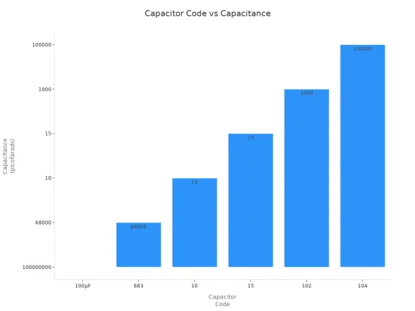
You find numeric codes stamped on many capacitors. These codes tell you the capacitance value. For two-digit codes, the number shows the value in picofarads. Three-digit codes use the first two digits as significant figures and the third as a multiplier. For example, "104" means 100,000 picofarads, or 0.1 microfarads. Some codes include a letter for tolerance. Numeric codes make it easy to check values quickly.
| Capacitor Code | Capacitance Value | Notes |
|---|---|---|
| 100μF | 100 microfarads | Breakdown voltage: 50V, negative leg indicated |
| 683 | 68,000 picofarads | Multiply leading digits by 10^3, breakdown voltage: 100V |
| 102 | 1,000 picofarads (1 nF) | Tolerance indicated by letter at end |
| 104 | 100,000 picofarads (0.1 µF) | Tolerance indicated by letter at end |
Alphanumeric Codes
Alphanumeric codes combine numbers and letters. You see these codes on modern capacitors. The first two digits show the significant value, and the third digit is the multiplier. Letters may show tolerance or voltage. For example, "104K" means 100,000 picofarads with ±10% tolerance. You need to know the unit, such as pF or nF, to read these codes correctly. Alphanumeric codes often appear on eia capacitor codes.
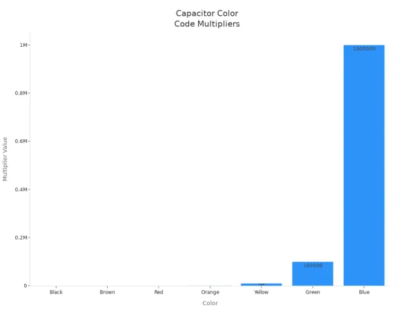
Color Codes
Older capacitors use color bands to show values. Each color stands for a digit, multiplier, or tolerance. You read the bands from left to right. Color codes are less common today, but you may still find them in older equipment.
| Color | 1st Digit | 2nd Digit | Multiplier | Tolerance |
|---|---|---|---|---|
| Black | 0 | 0 | 1 | ±20% |
| Brown | 1 | 1 | 10 | ±1% |
| Red | 2 | 2 | 100 | ±2% |
| Orange | 3 | 3 | 1,000 | ±3% |
| Yellow | 4 | 4 | 10,000 | ±4% |
| Green | 5 | 5 | 100,000 | ±5% |
| Blue | 6 | 6 | 1,000,000 | ±6% |
| Gold | - | - | - | ±5% |
| Silver | - | - | - | ±10% |
SMD Codes
Surface mount capacitors use special marking codes. SMD capacitor identification relies on short codes because of small sizes. You see system codes for type and material, feature codes for capacitance and voltage, and packaging codes for size. For example, "0105Y" means 1μF with 16V working voltage. SMD capacitor identification helps you choose the right part for integrated circuits.
| Code Part | Description | Example |
|---|---|---|
| System Codes | Component type and material | ECA |
| Feature Codes | Capacitance and voltage | 0105Y |
| Packaging Codes | Size and packaging method | K31 |
| Capacitance Value | Absolute value and power of 10 | 0105 = 1μF |
| Working Voltage | Voltage rating | Y = 16V |
| Tolerance | Capacitance tolerance | K = ±10% |
| Package Size | Package size | 3 = 0603 |
| Packaging Method | Packaging method | 1 = tape and reel width of 8mm |
Tip: SMD capacitor identification is important for modern circuit boards where space is limited.
Polarity Marks
Some capacitors, like electrolytic types, need correct polarity. You see a stripe or arrow for the negative terminal. A "+" sign marks the positive side. Longer leads mean positive, shorter leads mean negative. Case markings and chamfering also help you spot polarity. Correct polarity prevents damage to the capacitor and your circuit.
| Marking Method | Description |
|---|---|
| Stripe or Arrow | Shows the negative terminal. |
| '+' Sign | Marks the positive terminal. |
| Lead Length | Longer lead is positive, shorter is negative. |
| Case Marking | Negative side has a stripe or band with minus signs. |
Note: Always check capacitor markings for polarity before placing the component in your circuit.
Decoding Capacitor Values
Understanding how to decode capacitor values is a key skill for anyone working with electronic circuits. You can use a capacitor value chart to match markings to real-world values. This guide will help you read numeric markings, interpret color codes, understand SMD code basics, and check voltage ratings. You will also learn why units and E series standards matter when you use a capacitor value lookup.
Reading Numeric Markings
You often see numbers printed on capacitors. These numbers tell you the capacitance value. To decode them, follow these steps:
-
Identify the Capacitor Type
Check if you have a ceramic, electrolytic, tantalum, or another type. This helps you know which coding system to use. -
Look for Markings
Find numbers, letters, or symbols. For SMD capacitors, markings may be very small or missing. -
Decode Capacitance
Use the numbers to find the value. For example, "104" means 10 followed by four zeros in picofarads (100,000 pF or 0.1 µF). EIA capacitor codes like "A5" can also show values. -
Check Tolerance and Voltage
Letters like "K" mean ±10% tolerance. Numbers like "50" mean 50V voltage rating. -
Verify Polarity (if needed)
For polarized capacitors, check for a stripe or "+" sign to find the positive or negative terminal.
Tip: Always double-check the units. Mixing up pF, nF, and µF can cause big problems in your circuit.
Common mistakes include confusing units, misreading faded numbers, or missing voltage ratings. For example, a polyester capacitor with five color bands—Yellow, Red, Orange, White, and Red—shows 42nF with a ±10% tolerance. Small size and poor lighting can make it hard to read these codes.
Interpreting Color Codes
Some capacitors use color bands instead of numbers. You can use a reference chart to decode these bands. Here is how you read them:
- Start from the left side of the capacitor.
- The first band gives the first digit.
- The second band gives the second digit.
- The third band is the multiplier (number of zeros).
- The fourth band shows tolerance.
- The fifth band, if present, shows the temperature coefficient.
| Color Band | Significance |
|---|---|
| 1st | First significant digit of value |
| 2nd | Second significant digit of value |
| 3rd | Multiplier (number of zeros) |
| 4th | Tolerance in percentage |
| 5th | Temperature coefficient |
Note: Misreading color codes is common, especially if the colors are faded or hard to see. Always use good lighting and a reference chart.
SMD Code Basics
Surface-mount capacitors use short codes because of their small size. You can decode these codes by following a few basic rules:
- Codes show capacitance value, tolerance, voltage rating, and sometimes temperature coefficient.
- The EIA Standard Marking System uses three-digit or four-digit codes. For example, "105" means 1,000,000 pF or 1 µF.
- Some codes use letters for decimal points.
- Different standards and manufacturers may use unique codes. Always check the datasheet for your part.
Tip: If you cannot find a marking, use the manufacturer's documentation or a capacitor value lookup tool.
Voltage Ratings
Voltage rating is just as important as capacitance. The voltage rating tells you the highest voltage the capacitor can handle safely. If you go over this limit, the capacitor can fail or even explode.
- The capacitance of ceramic capacitors drops as you get close to the maximum voltage.
- Always pick a capacitor with a voltage rating 2-3 times higher than your circuit's working voltage.
- Exceeding the voltage rating shortens the capacitor's life and can damage your circuit.
- You can connect capacitors in series to handle higher voltages.
Remember: Always check the voltage rating before you install a capacitor.
The Importance of Units and E Series Standards
Capacitor values use three main units: picofarads (pF), nanofarads (nF), and microfarads (µF). Each unit fits a different range of values and applications. Understanding these units helps you avoid mistakes.
| Unit | Description | Common Applications |
|---|---|---|
| pF | Used for very small capacitor values, especially in RF circuits. | Ceramic capacitors, silver mica capacitors. |
| nF | Less common in older documents; often seen as 1000pF or 0.001µF. | General use in modern circuits. |
| µF | Measures larger capacitor values, especially in electrolytic capacitors. | Electrolytic, tantalum, and paper capacitors. |
- 0.1µF is the same as 100nF.
- 1000pF equals 1nF.
- 0.001µF also equals 1nF.
The E series standards (like E12 and E24) help you pick standard capacitor values. These series group values by tolerance:
| E Series | Tolerance |
|---|---|
| E6 | ±20% |
| E12 | ±10% |
| E24 | ±5% |
| E48 | ±2% |
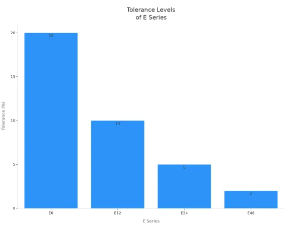
The E series gives you a systematic way to select values. You can always find a standard value that fits your needs. This makes the design process easier and helps control costs.
Using the right units and E series values ensures your circuit works as planned and stays reliable.
Practical Tips for Using Capacitor Value Charts
Reference Chart Usage
You can make your work easier by keeping a capacitor value chart nearby. This chart helps you match markings to real values quickly. When you see a code or color band, you can use the chart for a fast capacitor value lookup. Many engineers print charts or save them on their devices. You can find charts for eia capacitor codes, numeric codes, and color codes. If you work with integrated circuits, you will use these charts often. Charts also show voltage ratings and units, so you avoid confusion.
Tip: Use a laminated chart at your workstation. This protects the chart and makes it last longer.
Double-Check Values
Before you install a capacitor, you should always double-check its value. This step helps you avoid mistakes that can damage your circuit. You can use several methods to confirm the value:
- Visual Inspection: Look for signs of damage or leakage. A damaged capacitor may not work as expected.
- Use a Multimeter: Set your multimeter to capacitance mode. Connect the probes to the capacitor and compare the reading to the rated value.
- Capacitor Tester: Use a dedicated tester to measure capacitance, ESR, and leakage current. This gives you a complete picture of the capacitor’s health.
Checking values helps you catch errors before they affect your integrated circuits. You can prevent problems like signal distortion or power loss.
Avoiding Common Errors
You can avoid many common errors by following simple steps. Always check the units on the capacitor value chart. Mixing up pF, nF, and µF can cause your circuit to fail. Double-check the voltage rating before installation. If you use a capacitor with a low voltage rating, it may break down. Read markings carefully, especially on small or faded components. Use a reference chart for eia capacitor codes and color bands. If you are unsure, use a capacitor value lookup tool or check the datasheet.
Note: Careful checking saves time and money. You protect your circuit and keep your project running smoothly.
Common Mistakes with Capacitor Value Charts
When you work with electronic components, you need to avoid common mistakes that can lead to circuit problems. Using a capacitor value chart helps you select the right capacitor, but errors can still happen if you do not pay close attention.
Misreading Codes
You may find it hard to read the codes printed on a capacitor, especially if the markings are small or faded. Sometimes, you might mix up numbers or letters, which leads to choosing the wrong value. For example, reading "104" as "1004" changes the capacitance by a large amount. Always check the code twice and use a reference chart to confirm the value. If you see color bands, make sure you read them in the correct order. A mistake here can cause your integrated circuit to behave in unexpected ways.
Tip: Use a magnifying glass and good lighting when you read capacitor markings. This helps you avoid errors and keeps your circuit safe.
Overlooking Voltage
You must pay attention to the voltage rating on every capacitor. If you ignore this rating, your circuit may not work as planned. Using a capacitor with a voltage rating that is too low can cause several problems:
- Reduced lifespan of capacitors
- Circuit instability
- Unpredictable behavior in circuits
- Degradation of the oxide layer in electrolytic capacitors if not charged properly
Always choose a capacitor with a voltage rating higher than your circuit’s maximum voltage. This simple step protects your components and helps your integrated circuits run smoothly.
Confusing Units
Capacitors use different units like picofarads (pF), nanofarads (nF), and microfarads (µF). Mixing up these units can lead to major errors in your design. For example, selecting a 1 µF capacitor instead of a 1 nF capacitor changes the performance of your circuit. You can minimize confusion by checking the unit conversions in the table below:
| Unit | Equivalent Value |
|---|---|
| 1 µF | 1,000 nF |
| 1 µF | 1,000,000 pF |
| 1 nF | 1,000 pF |
Always use a capacitor value chart to confirm the correct unit before you install a capacitor. This habit helps you avoid costly mistakes and keeps your electronic projects reliable.
You can interpret capacitor value charts by following a few simple steps. First, check the markings for capacitance, voltage, and type. Use a table to compare different capacitor types and their marking styles:
| Type | Marking Style | Notes |
|---|---|---|
| Electrolytic | Value and voltage printed | Polarity matters |
| Polyester | Three-number notation | Non-polarized |
| Ceramic | Capacitance only | High voltage, non-polarized |
Understanding markings, units, and voltage ratings helps you select reliable parts for your circuits. For more tips, explore online guides, mobile apps, and keep a reference chart handy.
FAQ
How do you read a capacitor code like "104"?
You read "104" as 10 followed by four zeros in picofarads. That means 100,000 pF, which equals 0.1 µF. Always check the unit to avoid mistakes.
Why does voltage rating matter for capacitors?
Voltage rating tells you the highest voltage a capacitor can handle safely. If you use a capacitor with a lower rating, it may fail or damage your integrated circuit.
What is the difference between pF, nF, and µF?
These units measure capacitance. 1,000 pF equals 1 nF. 1,000 nF equals 1 µF. You must choose the right unit for your circuit to work correctly.
Can I use any capacitor in an integrated circuit?
You need to match the capacitor’s value, voltage rating, and type to your circuit’s needs. Using the wrong capacitor can cause errors or damage your components.
How do I check capacitor polarity?
Look for a stripe or minus sign for the negative side. The longer lead marks the positive side. Always install polarized capacitors in the correct direction.