The Role of Standard Capacitor Values in Electronics
The specific numbers on a capacitor, like 10µF or 47µF, are not random. They are part of a crucial system for electronics de

The specific numbers on a capacitor, like 10µF or 47µF, are not random. They are part of a crucial system for electronics design. The global capacitor market, valued at US$ 20,590 million in 2024, relies heavily on these standard capacitor values.
This system ensures every circuit is reliable and cost-effective. Selecting the correct value is essential. The right capacitor value from the available capacitor values ensures stability and performance.
Key Takeaways
- Standard capacitor values make electronics design and repair easier. They help keep costs low and ensure parts are available everywhere.
- The E-series system organizes capacitor values. It uses a special scale to cover many values without making too many different parts.
- Capacitor tolerance is how much its value can change. Different E-series numbers match different tolerance levels.
- Choosing the right capacitor means looking at more than just its value. You must also check its voltage rating, material, and size.
- A 0.1µF ceramic capacitor is very common. It helps keep power steady for computer chips.
The purpose of standard capacitor values
Standard capacitor values exist for very practical reasons. This system makes designing, manufacturing, and repairing electronics simpler and more efficient. It creates a universal language that engineers and manufacturers around the world understand, removing guesswork and ensuring consistency across the industry.
Streamlining manufacturing and cost
Standardization directly lowers manufacturing costs. When designers use common component values, manufacturers can produce parts in massive quantities. This economy of scale significantly reduces the price of each individual capacitor. This approach avoids the high cost of creating custom parts for every new design.
Product engineers follow key principles to manage costs:
- They design circuits using readily available, off-the-shelf components.
- They simplify the list of materials by using fewer types of parts.
- They design circuits that work with wider component tolerances, like 5% or 10%.
This system prevents a situation where two components have a slightly different value but function identically due to their tolerance ranges. By establishing a set of preferred numbers, manufacturers can focus production, boost efficiency, and deliver a reliable capacitor at a lower price.
Ensuring interchangeability and availability
A standardized system guarantees that components are interchangeable and widely available. An engineer in one country can design a circuit, and a manufacturer in another can build it without sourcing issues. This global consistency is possible thanks to international standards.
The International Electrotechnical Commission (IEC) publishes standard IEC 60063. This document specifies the preferred number series for resistors and capacitors. It provides the foundation for marking each component with its correct capacitance value, ensuring uniformity worldwide.
This standard means a 10µF capacitor from any certified manufacturer will meet the same specifications. This interchangeability simplifies repairs and maintenance. Technicians can easily find a replacement part, ensuring devices can be fixed quickly and reliably.
Decoding capacitor values: The E-series
The standard capacitor values follow a system called the E-series. This system, defined by the IEC 60063 standard, organizes component values into logical sets. Common series include E3, E6, E12, and E24. Each series number indicates how many steps or values exist within a single decade (e.g., from 1.0 to 10).
The logic of logarithmic steps
The E-series does not use simple, linear steps. Instead, it uses a logarithmic scale. This means the gap between each value increases as the value itself gets larger. For example, the E6 series has six values per decade: 1.0, 1.5, 2.2, 3.3, 4.7, and 6.8. This proportional spacing ensures that the relative difference between any two adjacent values remains roughly the same. This method provides good coverage across the entire range without creating an overwhelming number of parts. A designer can always find a suitable capacitance value nearby.
Matching tolerance to the series
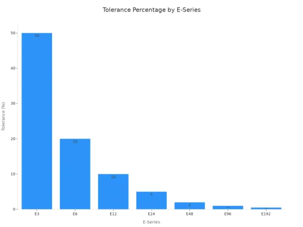
The E-series is directly linked to a capacitor's tolerance. This connection prevents any overlap between the tolerance ranges of adjacent capacitor values. A lower E-series number corresponds to a wider tolerance.
Electrolytic capacitors often have a wide tolerance of ±20%. They use the E3 and E6 series. These are perfect for filtering and bypassing, where a precise capacitance value is not critical. A generic ceramic capacitor value from the E3 series will work for most general applications.
For designs needing more precision, like oscillators, engineers use higher E-series. A ceramic capacitor value from the E12 or E24 series offers a tighter tolerance. The table below shows the direct relationship between the series and its typical tolerance.
| E-series | Tolerance |
|---|---|
| E3 | ~40% (or >20%) |
| E6 | 20% |
| E12 | 10% |
| E24 | 5% |
| E48 | 2% |
| E96 | 1% |
This chart visually demonstrates how tolerance narrows as the E-series number increases.
Choosing the right series ensures the selected capacitor meets the circuit's performance needs without overpaying for unnecessary precision.
Selecting the right capacitor values
Choosing the correct capacitance value is a critical step in circuit design. The selection process depends heavily on the capacitor's role in the circuit. Different applications, such as decoupling or filtering, have unique requirements that guide an engineer's choice.
Decoupling and bypassing applications
Decoupling capacitors are essential for stabilizing the power supply voltage for integrated circuits (ICs). ICs draw current in fast, short bursts, which can cause voltage drops and introduce noise into the power lines. Decoupling capacitors act as small, local energy reservoirs to supply these current bursts, keeping the voltage stable.
A common and effective practice is to use multiple capacitor values together. Using values like 10µF, 1µF, and 0.1µF in parallel creates a power distribution network (PDN) that can handle a wide frequency range of noise. Larger capacitors are effective at filtering low-frequency noise, while smaller capacitors handle high-frequency noise. This combination ensures comprehensive noise suppression across a broad spectrum.
The physical size of a capacitor is directly related to its high-frequency performance due to a property called Equivalent Series Inductance (ESL). ESL is an unwanted inductance inherent in every capacitor.
- The distance between a capacitor's terminations significantly influences its ESL.
- Shorter current paths and compact construction lead to lower inductance.
- Generally, a larger physical size and longer leads result in a higher ESL. For example, a 47µF electrolytic capacitor might have an ESL of 30 nH, while a small 0.1µF ceramic disc capacitor could have an ESL as low as 7 nH.
This is why a small 0.1µF ceramic capacitor value is the industry standard for high-frequency decoupling. Its low ESL allows it to respond quickly to the fast current demands of modern ICs. Electrolytic capacitors, with their higher ESL and slower chemical-based operation, are not suitable for this task.
Expert Insight: Practical circuit design often involves selecting components for high-speed digital systems. For instance, Nova Technology Company (HK) Limited, a HiSilicon-designated solutions partner, emphasizes the use of Multi-Layer Ceramic Capacitors (MLCCs) for their ultra-low ESR/ESL properties. This is crucial for suppressing GHz-range noise generated by fast-switching transients in advanced processors, preventing logic errors and EMI issues.
The table below compares the key features of ceramic and electrolytic capacitors for high-frequency tasks.
| Feature | Ceramic Capacitors | Electrolytic Capacitors |
|---|---|---|
| Frequency Response | Excellent (MHz to GHz) | Good (DC to kHz) |
| ESR | Low | Higher |
| High-frequency performance | Excellent for RF and high-speed digital circuits | Poor performance above ~100kHz |
| Applications | High-frequency bypass (0.1µF), power supply decoupling (0.1µF typical) | Not suitable for high-frequency applications |
Filtering and timing circuits
Capacitors are also fundamental components in filtering and timing circuits. In these applications, the capacitance value directly determines the circuit's behavior, such as the cutoff frequency of a filter or the time delay of a timer. The selection process here is more calculation-driven.
First, an engineer calculates the ideal capacitance value based on the desired performance. For example, in a 555 timer circuit, the time delay (T) is determined by a resistor (R) and a capacitor (C). The formula is:
T = 1.1 x R x C
An engineer can rearrange this formula to solve for the required capacitance value if the desired time delay and a chosen resistor value are known.
Once the ideal value is calculated, the next step is to select the closest available standard capacitor value from an appropriate E-series. Imagine a calculation results in an ideal capacitance of 3.5µF for a filter with a 5% tolerance requirement. The designer would consult the E24 series (5% tolerance).
- Identify the ideal value: 3.5µF.
- Find the bracketing standard values: The E24 series includes 3.3µF and 3.6µF.
- Calculate the difference: The difference between 3.5µF and 3.3µF is 0.2µF. The difference between 3.5µF and 3.6µF is 0.1µF.
- Select the closest value: 3.6µF is closer to the ideal value of 3.5µF.
Therefore, the engineer would choose the 3.6µF capacitor. In most RC circuits, the slight difference between the calculated value and the chosen standard value has a minimal impact on performance, especially when component tolerances are already factored into the design. This practical approach ensures the circuit functions reliably without the need for expensive, custom-value components.
Beyond capacitance: Key capacitor factors
Selecting a capacitor involves more than just finding the right capacitance value. Engineers must also consider other critical factors. The voltage rating, dielectric material, and physical package size all play a significant role in a circuit's reliability and performance. Making the right choice ensures the capacitor functions safely and effectively.
Voltage rating and dielectric material
The voltage rating is a crucial safety specification. It defines the maximum continuous voltage a capacitor can handle. Exceeding this voltage rating can cause the dielectric material to break down. This failure leads to a short circuit, overheating, and even an explosion, posing a serious risk to the equipment and individuals.
Safety Tip: Engineers apply a practice called voltage derating to improve reliability. A common rule for a ceramic capacitor is to choose a voltage rating at least twice the circuit's operating voltage. For example, a 35V rated capacitor should only be used up to 28V in some applications, which is 80% of its full voltage rating. This safety margin protects the capacitor from voltage spikes.
The dielectric material also affects a capacitor's behavior.
- A ceramic capacitor uses materials like barium titanate. This makes a ceramic capacitor excellent for high-frequency signals.
- Electrolytic capacitors use an oxide layer to achieve a very high capacitance value in a small volume.
- Film capacitors use organic films like polypropylene. They have very low loss, making them ideal for equipment that runs for long periods.
Each material offers a different performance value, so the choice depends on the application's specific needs. A ceramic capacitor is a frequent choice for many designs.
Package size and high-frequency performance
A capacitor's physical size directly impacts its high-frequency performance. Smaller packages, like the 0402 size, are preferred for high-speed circuits. This is because they have lower parasitic inductance. Parasitic inductance is an unwanted property that can disrupt signal integrity at frequencies above 100 MHz. A smaller ceramic capacitor has less of this effect.
Another important property is Equivalent Series Resistance (ESR). ESR is the total internal resistance of a capacitor to alternating current. A lower ESR value is better for high-frequency applications because it reduces power loss and heat generation. The package size, construction, and material of a ceramic capacitor all influence its ESR value. Choosing a ceramic capacitor with a low ESR and a small package size is key for modern, high-speed digital electronics. This is why a specific ceramic capacitor value is often paired with a specific package.
Standard capacitor values are a powerful tool for reliable circuit design. The E-series system provides a logical guide for selection. Choosing the right capacitor means balancing the required capacitance value with other factors. The selected value must align with the correct voltage rating. A component's voltage is a critical safety value. The circuit voltage determines the necessary voltage rating.
Actionable Tip: Start your next circuit with a 0.1µF capacitor for decoupling. This common capacitance value helps prevent voltage dips. The capacitor's voltage rating should always exceed the operating voltage.
FAQ
How do you read the code on a ceramic capacitor?
A person can learn how to read ceramic capacitor codes easily. The first two digits are the significant figures. The third digit is the multiplier, which tells you how many zeros to add. The value is in picofarads (pF). A ceramic capacitor is simple to identify this way.
Why is a 0.1µF ceramic capacitor so common?
Engineers use a 0.1µF ceramic capacitor for decoupling. It removes high-frequency noise from power lines. This specific ceramic capacitor has low inductance. Its small size helps it react quickly to stabilize voltage for integrated circuits. A ceramic capacitor of this value is an industry standard.
What is the difference between a ceramic capacitor and an electrolytic capacitor?
A ceramic capacitor is non-polarized and works well at high frequencies. An electrolytic capacitor is polarized and offers high capacitance in a small size. People use a ceramic capacitor for filtering noise. They use electrolytic capacitors for power supply storage.
How do you know how to read ceramic capacitor markings?
The method for how to read ceramic capacitor markings is straightforward. A code like "104" on a ceramic capacitor means 10 followed by four zeros. This equals 100,000 pF, or 0.1µF. This system simplifies identifying the value of a ceramic capacitor.
What does the letter on a ceramic capacitor mean?
The letter after the number code indicates the tolerance. For example, "J" means ±5%, "K" means ±10%, and "M" means ±20%. This letter helps engineers choose a component with the right precision. Knowing how to read ceramic capacitor letters is important for circuit accuracy.