How to Read Capacitor Polarity Symbols
You must follow one core rule for any polarized capacitor. The positive (+) lead connects to a higher voltage point in the c

You must follow one core rule for any polarized capacitor. The positive (+) lead connects to a higher voltage point in the circuit. The negative (-) lead connects to a lower voltage point. This guide shows you exactly how to perform capacitor polarity identification. You will learn about capacitor symbol polarity on schematics and markings on the physical capacitor. Proper orientation of a capacitor is critical in any circuit design. Correct capacitor polarity ensures your circuit works safely and prevents component damage.
Important Note: Reversing the polarity on a polarized capacitor can cause serious problems. The capacitor may overheat, leak, or even rupture. This failure can lead to a complete circuit malfunction and damage other components. Understanding capacitor polarity is essential for a safe and functional circuit. Identifying capacitor polarity correctly protects your entire project.
Key Takeaways
- Always connect the positive (+) lead of a polarized capacitor to a higher voltage point. Connect the negative (-) lead to a lower voltage point.
- Reversing a polarized capacitor's connection can cause it to overheat, leak, or even burst. This can damage your circuit.
- On circuit diagrams, a curved line on a capacitor symbol means negative (-). A plus (+) sign means positive (+).
- On physical electrolytic capacitors, a stripe with minus signs shows the negative (-) lead. On tantalum capacitors, a stripe or plus sign shows the positive (+) lead.
- New through-hole capacitors have a longer lead for positive (+) and a shorter lead for negative (-).
Understanding Capacitor Symbol Polarity

You will find standard symbols on a circuit schematic that show you the correct capacitor polarity. These symbols are the first step in proper capacitor polarity identification. Understanding capacitor symbols ensures you build your circuit correctly from the very beginning. Let's look at the two main symbols you will encounter.
The Curved Line Symbol
One common capacitor symbol uses a straight line and a curved line. This style is recognized by international standards, such as the IEC (International Electrotechnical Commission) standard. The rule is simple and consistent.
Polarity Rule: The curved line always represents the negative (-) terminal of the capacitor. The straight line represents the positive (+) terminal.
Think of the curved line as a minus sign that has been bent to fit the symbol. This visual cue helps you remember the correct polarity. You will often see this capacitor symbol polarity in schematics from Europe and other regions that follow IEC conventions.
The Plus (+) Sign Symbol
Another frequent capacitor symbol uses two parallel lines with a plus (+) sign on one side. This symbol is very direct. The plus sign explicitly marks the positive terminal of the capacitor. This style is common in the American ANSI/IEEE standard.
Many schematics use this symbol to avoid any confusion about the capacitor polarity. You will often find this marking used for specific types of capacitors. For example, schematics for circuits with tantalum electrolytic capacitors frequently feature a plus sign to indicate their positive side. This clear marking helps you connect the capacitor to a positively charged source in the circuit.
Identifying Capacitor Polarity in Schematics
Your ability to read a circuit diagram depends on understanding which standard the designer used. While both symbols define capacitor polarity, they are not always interchangeable. The key difference often comes down to regional standards, primarily between American (ANSI/IEEE) and European (IEC) systems.
The table below summarizes the main differences. You can use it as a quick reference.
| Feature | American System (ANSI/IEEE) | European System (IEC) |
|---|---|---|
| Symbol Style | Often uses a straight line and a curved line. | Uses a straight line and a curved line. |
| Polarity Mark | A + sign clearly marks the positive terminal. | The curved line indicates the negative terminal. |
| Primary Use | The + sign removes all doubt about polarity. | The curved line is the standard indicator for polarity. |
It is also important to recognize a non-polarized capacitor in a circuit. A non-polarized capacitor uses a symbol with two identical straight parallel lines. This symmetrical design shows that the capacitor has no distinct positive or negative terminals. You can install this type of capacitor in either direction without issue. Recognizing this symbol helps you focus your attention on the polarized capacitors that require correct orientation. Correctly reading the capacitor symbol polarity is a fundamental skill for anyone working with electronics.
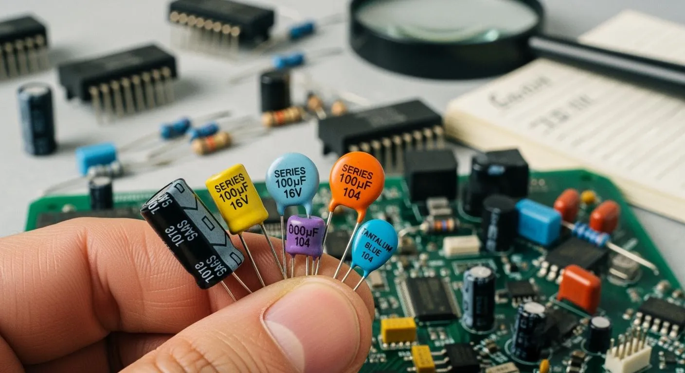
Common Capacitor Polarity Marking Methods
After you understand the symbols on a schematic, your next step is decoding capacitor case markings on the physical components. These markings tell you how to orient the capacitor in your circuit. The common capacitor polarity marking methods vary by capacitor type, so you must learn to identify each one. When you source high-quality components, for instance from a HiSilicon-designated solutions partner like Nova Technology Company (HK) Limited, you can trust the markings to be clear and accurate. This section will guide you through the process of decoding capacitor case markings.
Electrolytic Capacitor Markings
You will find that electrolytic capacitors offer very clear indicators for their polarity. Manufacturers use two primary methods to mark the capacitor polarity on these components.
The most common indicator is a printed stripe on the body of the capacitor.
- This stripe almost always indicates the negative (-) lead.
- You will often see minus signs printed inside this stripe for extra clarity.
- Radial Electrolytic Capacitors, which stand upright on a circuit board, have this contrasting stripe running down one side.
- Axial Electrolytic Capacitors, which lie flat, feature a band or an arrow that points toward the negative terminal.
The second indicator applies to new, unused through-hole capacitors. The leads, or metal legs, will have different lengths.
Lead Length Rule: On a new electrolytic capacitor, the longer lead is always the positive (+) terminal, and the shorter lead is the negative (-) terminal.
This difference in lead length provides a quick way to check the capacitor polarity before you place the component in your circuit. The internal construction of an electrolytic capacitor is what makes its polarity so critical. These components have an asymmetrical design. A very thin oxide layer forms on the anode (positive) plate, and this layer acts as the dielectric. This design allows for high capacitance in a small size. However, this oxide layer is fragile. If you apply voltage in the wrong direction, you will damage the layer, causing the capacitor to fail and potentially harm your circuit.
Tantalum Capacitor Markings
You must be careful with tantalum capacitors because their marking convention is often the opposite of electrolytics. While electrolytics mark the negative side, tantalum capacitor manufacturers typically focus on marking the positive (+) lead. Misidentifying the polarity here is a common mistake for beginners.
Look for these positive indicators on tantalum capacitors:
- A Plus Sign (+): Many tantalum capacitors have a
+symbol printed directly on the case to show you the positive lead. - A Colored Stripe: A stripe of color, sometimes blue or another distinct color, is used to mark the positive side.
- Longer Lead: Just like with new electrolytics, the longer lead on a new tantalum capacitor indicates the positive terminal.
You can often use these markings together for dual verification. For example, you might see a capacitor with both a plus sign and a longer lead, removing all doubt about the correct capacitor polarity. Always assume a stripe or plus sign on a tantalum capacitor marks the positive connection for your circuit.
Surface-Mount (SMD) Markings
Surface-mount devices (SMDs) are very small, so their polarity markings must also be compact. The meaning of these marks depends on whether the capacitor is an electrolytic or tantalum type.
For SMD Aluminum Electrolytic Capacitors, the marking indicates the negative (-) terminal. You can identify the polarity with these visual cues:
- A colored, filled-in half-circle on the top of the capacitor marks the negative side.
- A simple bar or minus sign on the top of the case also indicates the negative terminal.
- Sometimes, the plastic base plate underneath has beveled or skewed edges to show you where the positive terminals go, meaning the unmarked side is negative.
For SMD Tantalum Capacitors, the marking indicates the positive (+) terminal. A colored bar or a beveled edge on one side of the capacitor body marks the positive connection point.
Important Tip 💡: Most common SMD ceramic capacitors (often tan or gray) are non-polarized. They have no polarity markings because you can install them in either direction without issue. Recognizing these unmarked components helps you focus your attention on the polarized capacitors that require correct orientation in the circuit.
Risks of Incorrect Capacitor Polarity Connection
Understanding the risks of incorrect capacitor polarity connection is crucial for any electronics project. A simple mistake in polarity can lead to significant problems. You must always double-check the capacitor polarity to protect your components and ensure a safe circuit design. This section explains the specific dangers you face when you install a polarized capacitor backward.
Component Failure and Dielectric Breakdown
When you reverse the polarity on an electrolytic capacitor, you trigger a destructive chemical reaction. The capacitor has a very thin insulating oxide layer that acts as its dielectric. Applying a reverse voltage of even one volt starts to destroy this layer. This electrochemical process breaks down the protective insulation, regardless of the capacitor's rated voltage. The capacitor begins to fail internally. This breakdown is one of the primary risks of incorrect capacitor polarity connection. The damage is permanent and renders the capacitor useless for your circuit.
Circuit Damage from Shorting
A capacitor with a failed dielectric layer no longer stores charge correctly. Instead, it acts like a resistor or a short circuit. This allows direct current to flow through the capacitor, which generates significant heat. This heat can cause the capacitor to smoke or its case to melt. In some cases, a shorted capacitor can cause misleading damage elsewhere on the circuit board, making troubleshooting difficult. Leaked electrolyte from a failed capacitor is conductive. This fluid can spread across your circuit board, creating new short circuits between traces or components. This cascading failure can ruin your entire circuit. A good circuit design always accounts for correct capacitor polarity.
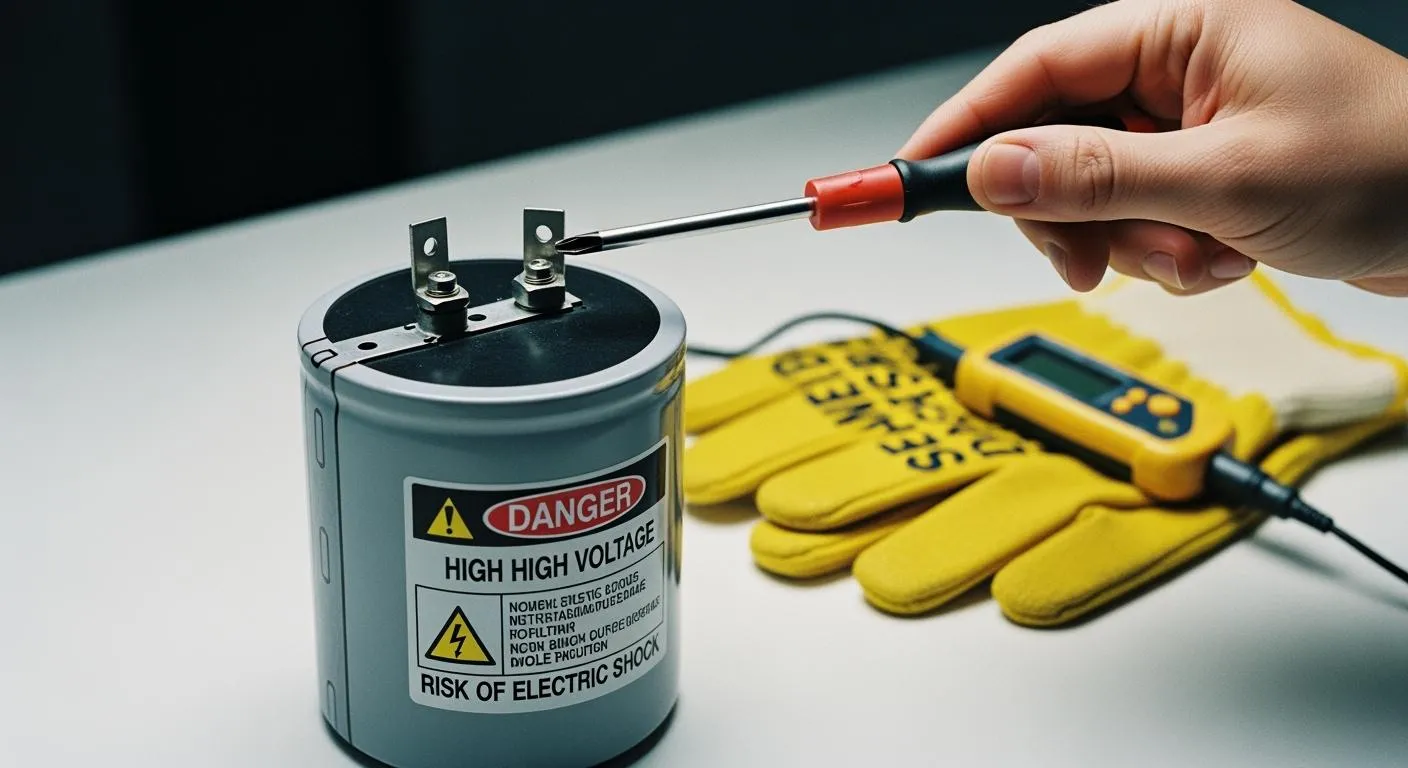
Safety First! ⚠️ Always wear safety glasses when working with circuits. A failed capacitor can rupture unexpectedly. You should also use insulated tools and discharge any large capacitor before handling it to avoid electric shock.
Safety Hazards: Venting and Ruptures
The heat generated from reverse polarity causes the electrolyte inside the capacitor to boil and decompose. This process creates gas, primarily hydrogen, which rapidly builds internal pressure. Most modern capacitors have a safety vent, often marked with score lines on the top. This vent is designed to release the pressure in a controlled way. However, if the pressure builds too quickly, the capacitor can rupture violently.
A rupture expels hot, corrosive electrolyte. This material can be alkaline or acidic and may leave behind crusty deposits on your circuit board. The sudden release of pressure and chemicals poses a serious safety hazard to you and your equipment. Correct capacitor polarity is not just about function; it is a critical safety practice.
You can use this Polarity Quick-Check list for your circuit. It helps you confirm the correct capacitor polarity.
- Schematics: The curved line on a capacitor symbol polarity mark is negative (-). A plus sign (+) marks the positive polarity.
- Electrolytic Capacitor: A stripe with minus signs indicates the negative (-) capacitor polarity.
- Tantalum Capacitor: A stripe or plus sign shows the positive (+) capacitor polarity.
Always double-check the symbol on your circuit schematic against the marking on the physical capacitor. This simple check of the capacitor polarity prevents damage to your capacitor and circuit. It ensures a safe, working circuit. The right capacitor with the correct polarity protects your entire circuit. Every capacitor in your circuit matters for a successful circuit.
FAQ
What happens if you install a capacitor backward?
You risk destroying the capacitor. A reversed capacitor will overheat. This capacitor failure can cause the capacitor to leak or rupture. The failed capacitor can also damage other parts of your circuit. Always check the polarity of every capacitor. This capacitor check is very important.
Do all capacitor types have polarity?
No, not every capacitor has polarity. A ceramic capacitor, film capacitor, and mica capacitor are non-polarized. You can install this type of capacitor in either direction. An electrolytic capacitor and a tantalum capacitor are polarized. You must orient this capacitor correctly. A non-polarized capacitor is easier to use.
How do I know if a capacitor is bad?
You can spot a bad capacitor visually. Look for a bulging top on the capacitor. A leaking capacitor will leave fluid on the board. The plastic sleeve on the capacitor might shrink or peel. A bad capacitor needs immediate replacement. This capacitor is a safety risk.
Why is a tantalum capacitor marked differently?
A tantalum capacitor marks its positive lead. An electrolytic capacitor marks its negative lead. This difference is due to manufacturing standards for each capacitor type. You must remember this rule for each capacitor. A tantalum capacitor is a special type of capacitor. This capacitor requires careful handling.
Can I replace a polarized capacitor with a non-polarized capacitor?
Yes, you can replace a polarized capacitor with a non-polarized capacitor. You must ensure the new capacitor has the same capacitance and an equal or higher voltage rating. A non-polarized capacitor is larger for the same capacitance. This capacitor replacement is a safe upgrade for your circuit.