Mastering Capacitor Polarity Symbols In Circuits
A simple capacitor polarity symbol on a schematic is a critical instruction. Correctly identifying capacitor polarity preven
A simple capacitor polarity symbol on a schematic is a critical instruction. Correctly identifying capacitor polarity prevents circuit failure and component damage. This capacitor polarity marking is the key to safety. A reversed capacitor polarity can cause a capacitor to fail, sometimes with dangerous results. This guide helps builders master the capacitor polarity symbol. Understanding the polarity of a capacitor ensures every project is safe and successful.
Key Takeaways
- Always check capacitor polarity symbols on circuit diagrams and physical components. This prevents mistakes.
- Connecting a polarized capacitor backward can cause it to overheat, explode, or damage the entire circuit. This is very dangerous.
- Use the 'Triple-Check Method' to match the schematic, PCB, and physical capacitor markings. This ensures correct installation.
- Electrolytic and tantalum capacitors are polarized. They must be installed in the correct direction for the circuit to work right.
Identifying Capacitor Polarity
Correctly identifying capacitor polarity is a fundamental skill. It begins with understanding the language of circuit diagrams and component markings. A builder must learn to read both the schematic and the physical capacitor to prevent errors. This process involves recognizing symbols, inspecting physical components, and matching them to the circuit board.
The Capacitor Polarity Symbol
Circuit schematics use specific symbols to communicate information. The capacitor polarity symbol is a crucial instruction for any polarized component. There is a clear visual difference between symbols for polar capacitors and non-polarized ones.
- Non-Polarized Capacitors: These components, like ceramic or film types, do not have a required polarity. Their schematic symbol features two simple, parallel straight lines. This symmetrical design shows they can be installed in either direction.
- Polarized Capacitors: These components must be installed correctly. The schematic symbol for polar capacitors clearly indicates which side is positive and which is negative.
The table below shows the most common symbols. Understanding this capacitor polarity symbol is the first step in building a reliable circuit.
| Capacitor Type | Schematic Symbol | Description |
|---|---|---|
| Non-Polarized | | | | Two parallel, equal-length straight lines. No polarity. |
| Polarized (US/IEC) | | ) | A straight line for the positive (+) terminal and a curved line for the negative (-) terminal. |
| Polarized (Alternate) | [+] | | | Two parallel lines with a plus sign (+) indicating the positive terminal. The polarity is explicit. |
Physical Markings on Capacitors
Physical capacitor markings directly indicate the component's polarity. Manufacturers use several standard methods to mark the polarity on the body of a capacitor.
For through-hole components, lead length is a common indicator on new parts.
- Longer Lead: The longer lead on a new through-hole capacitor is almost always the positive (+) terminal.
- Shorter Lead: The shorter lead corresponds to the negative (-) terminal.
Note: Always double-check with other markings. Leads may be trimmed, making lead length an unreliable indicator for used or pre-cut components.
For radial electrolytic capacitors, a prominent stripe on the can is the most reliable indicator. This colored stripe, often white or gray, contains minus symbols (-) and points to the negative lead. This marking system is standard for aluminum polymer and other electrolytic capacitors.
Tantalum capacitors have their own distinct capacitor markings.
- Through-Hole Tantalums: These often have a small plus sign (+) printed on the body to mark the positive lead. The longer lead is also positive.
- SMD Tantalums: Surface-mount tantalum capacitors typically use a colored bar or a bevel on the case to mark the positive (+) side.
The polarity of a capacitor is always clearly marked. A builder just needs to know where to look.
Matching Symbols to Components
The final step is to match the physical capacitor to its designated spot on the Printed Circuit Board (PCB). The PCB's silkscreen layer provides a guide for placing each component. This guide ensures the proper orientation of all polar capacitors.
PCB designers use several common silkscreen markings to indicate capacitor polarity.
- A plus sign (+) printed on the board marks the hole for the positive lead.
- A shaded or filled area on the silkscreen outline shows where the negative side of the capacitor should be.
- A beveled edge on the component outline can indicate the positive side of an SMD capacitor.
- A circle with a plus on one side and an arc on the other can mimic the capacitor itself.
A technician must ensure the physical capacitor polarity aligns with the silkscreen marking. For example, the negative stripe on an electrolytic capacitor must align with the shaded area on the PCB. The plus sign on a tantalum capacitor must align with the + on the board. This careful matching of the capacitor polarity symbol on the board to the physical component's polarity is essential for circuit function.
The Importance of Capacitor Polarity
Understanding capacitor polarity is more than just matching symbols. It is a fundamental rule for circuit safety and reliability. The internal structure of polar capacitors dictates their orientation. Ignoring the correct capacitor polarity can lead to component failure and circuit-wide damage. Proper connection ensures the capacitor functions correctly for optimal performance.
The Science of Polarized Dielectrics
Polarized capacitors have a special internal design. Their insulating layer, called the dielectric, is created through an electrochemical process. This process is known as anodic oxidation. A manufacturer applies a positive voltage to the anode material (like aluminum or tantalum) inside an electrolytic bath. This action forms a very thin but strong oxide layer. The thickness of this layer depends on the voltage used during its formation. This oxide layer is the dielectric for the capacitor.
This formation process gives the capacitor its polarity. The dielectric layer is designed to block current when the voltage is applied in the correct direction. The anode metal has a positive polarity. The electrolyte has a negative polarity. This setup allows the capacitor to store a large amount of charge. However, this unique structure means the capacitor's performance depends entirely on the correct voltage polarity. The component must be installed with the correct capacitor polarity to maintain its insulating properties.
Risks of a Reversed Connection
Connecting a polarized capacitor with reversed polarity is extremely dangerous. The dielectric oxide layer is not designed to handle voltage in the wrong direction. When reversed polarity is applied, the insulating layer begins to break down.
- The dielectric layer, often aluminum oxide, can dissolve through electrolysis.
- This loss of insulation causes the capacitor to act like a short circuit.
- Current flows freely through the capacitor, causing it to heat up rapidly.
This rapid heating can have dramatic results. The electrolyte inside the capacitor can boil, creating immense internal pressure.
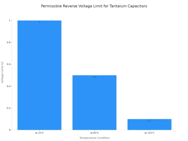
Tantalum capacitors are also very sensitive to reversed polarity. Applying a reverse voltage causes high leakage currents. This can quickly lead to a short-circuit failure. While they can handle a very small reverse voltage, it is extremely limited and decreases with temperature. Exceeding these limits will ruin the capacitor.
| Capacitor Condition | Permissible Reverse Voltage Limit |
|---|---|
| Solid Tantalum (at 25°C) | 10% of Rated Voltage or 1V (whichever is smaller) |
| Solid Tantalum (at 85°C) | 5% of Rated Voltage or 0.5V (whichever is smaller) |
| Solid Tantalum (at 125°C) | 1% of Rated Voltage or 0.1V (whichever is smaller) |
Any capacitor subjected to reversed polarity beyond its tiny tolerance should be discarded. Even if it seems to work, hidden damage compromises its long-term performance and safety. The risk of future capacitor breakdown is too high.
How Reversal Damages a Circuit
A single capacitor connected with reversed polarity can trigger a chain reaction of failures. When the capacitor fails as a short circuit, it creates a low-resistance path for current. This can have devastating effects on the entire circuit.
A shorted capacitor can draw excessive current from the power supply. This may cause the power supply to shut down or fail completely. In older electronics, a failed capacitor can short out a power rail and destroy rare components like transformers. The failure of one small capacitor can lead to expensive and difficult repairs.
In switching power supplies, a damaged capacitor can cause an unstable output voltage or prevent the supply from working at all. This unstable voltage creates logical chaos in digital circuits. The incorrect signal levels can cause a device to malfunction or not turn on. A bad signal from the power supply affects the entire system's performance. The correct capacitor polarity is essential for a clean power signal. Polar capacitors are critical for filtering the power signal, and their failure introduces noise. This is why respecting the polarity of polar capacitors is a non-negotiable rule in electronics.
Common Polarized Capacitors and Applications
Different types of polar capacitors have specific jobs in electronic circuits. Their unique properties make them suitable for certain applications. Designers choose a specific capacitor based on factors like size, capacitance, and cost. Understanding the capacitor polarity is crucial for their function.
Electrolytic Capacitors in Power Supplies
Power supply designers often use aluminum electrolytic capacitors. These components are excellent for smoothing and buffering rectified DC voltages. Their main advantage is a high capacitance density, which allows them to store a lot of energy in a small package. This feature is vital for voltage regulation. The correct capacitor polarity ensures the capacitor works as intended.
These polar capacitors are inexpensive and come in a wide range of sizes and values. This makes them a popular choice for power supplies in consumer electronics and industrial equipment. A capacitor in a power supply helps create a stable output signal. The correct polarity of the capacitor is essential for this task.
| Category | Voltage Rating | Capacitance Rating |
|---|---|---|
| Low Voltage | Up to 50V | Less than 10 µF |
| Medium Voltage | 50V - 250V | 10 µF - 100 µF |
| High Voltage | Above 250V | Above 100 µF |
Tantalum Capacitors in Compact Devices
Tantalum capacitors are another type of polar capacitors. They are known for their small size and high reliability. These features make them perfect for compact devices where space is limited, such as smartphones, tablets, and laptops. The capacitor polarity must be correct for stable performance.
These components offer excellent performance for their size. They provide stable capacitance and low leakage current, which is critical for battery-powered devices. The correct polarity helps achieve optimal performance. A tantalum capacitor is often used for power signal filtering and voltage regulation on crowded circuit boards. Their robust performance improves overall device durability. Key applications include:
- Power Supply Filtering: A tantalum capacitor provides a clean power signal for sensitive components.
- Signal Coupling: They help transfer an AC signal between circuit stages.
- Voltage Regulation: They ensure a steady voltage for consistent device operation.
Respecting the capacitor polarity of these electrolytic capacitors ensures the long-term performance and safety of the device.
Ensuring Correct Polarity Connection
A builder must guarantee the correct polarity connection before powering any circuit. Following a systematic process prevents component damage and ensures safety. This involves careful inspection and, when necessary, verification with test equipment. Adopting these habits is essential for every electronics project.
The Triple-Check Method
The most reliable way to ensure correct capacitor polarity is the Triple-Check Method. This simple but effective process confirms alignment between the design, the board, and the component. A technician should make this a mandatory habit.
- Check the Schematic: First, identify the capacitor polarity symbol on the circuit diagram. Note which pin is positive (+) and which is negative (-).
- Check the PCB Silkscreen: Next, find the component's location on the PCB. The silkscreen should have a marking, like a
+sign or a shaded area, indicating the correct orientation. - Check the Physical Capacitor: Finally, inspect the physical capacitor. Match its negative stripe or positive lead marking to the corresponding indicator on the PCB.
All three sources must agree. If there is any mismatch, a builder must stop and investigate the discrepancy before proceeding.
💡 Heads-Up: Discrepancies are more common than one might think.
- Faded or damaged silkscreen markings can make orientation unclear.
- Assembly drawings can sometimes have ambiguous instructions.
- Missing polarity markings on the board require a technician to trace the circuit back to a known point.
Using a Multimeter for Verification
When markings are absent or unclear, a multimeter can help determine a capacitor's polarity. A technician can use the diode check or resistance mode. When connecting the probes to a discharged capacitor, the meter will show a brief low resistance reading one way and a higher or infinite reading the other way. The connection that shows higher resistance usually has the red probe on the positive terminal of the capacitor.
This method helps confirm the capacitor polarity. However, it is not always foolproof, especially for an in-circuit capacitor. Some modern polarity protection circuits can also complicate readings. For absolute certainty, it is best to test the capacitor out of the circuit. Advanced polarity protection circuits can help prevent damage if a mistake occurs.
⚠️ Caution: Testing a capacitor while it is still in the circuit can lead to inaccurate readings. Other components can interfere with the measurement, causing false results. To ensure accuracy, a technician should remove the capacitor from the circuit before testing its polarity.
Correctly identifying capacitor polarity is a non-negotiable skill. A builder must respect the polarity of every polarized capacitor. Ignoring the correct capacitor polarity can destroy the capacitor's dielectric, leading to failure or even an explosion. The polarity of a capacitor is a critical instruction. A successful project depends on getting the capacitor polarity right every time. A builder ensures circuit safety by checking the polarity of each capacitor.
💡 Final Check: Always perform the "Triple-Check" before applying power. A builder must confirm the schematic, PCB, and capacitor markings all agree on the correct capacitor polarity. This habit prevents damage to the capacitor and the entire circuit.
FAQ
Can a builder use a non-polarized capacitor in place of a polarized one?
Yes, a non-polarized capacitor can replace a polarized capacitor if the capacitance and voltage ratings match. The non-polarized capacitor has no orientation requirement. However, a polarized capacitor is often smaller for the same capacitance, so a non-polarized capacitor might not fit on the board.
Do all capacitors have polarity?
No, not every capacitor has polarity. Ceramic, film, and silver mica capacitors are non-polarized. A builder can install this type of capacitor in any direction. Only electrolytic and tantalum capacitors have a required polarity. This capacitor type must be installed correctly.
What happens if a capacitor is installed backward but does not explode?
Even if a reversed capacitor does not fail immediately, it is permanently damaged. The dielectric layer breaks down, causing high internal leakage. This damaged capacitor will have poor performance and is likely to fail later. A technician should always replace a reversed capacitor.
Why is the positive lead longer on a new capacitor?
Manufacturers make the positive lead longer on a new through-hole capacitor for quick identification. This standard helps builders orient the capacitor correctly during assembly.
- The long lead indicates the positive terminal.
- The short lead indicates the negative terminal.
This simple feature makes placing the capacitor easier.