

How to Identify and Use the Continuity Test Symbol
You can spot the continuity test symbol on your multimeter by looking for a small diode icon with sound waves or a
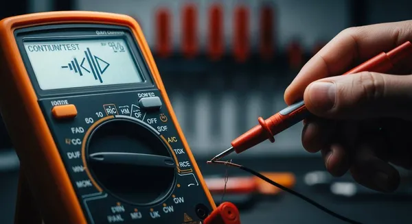
You can spot the continuity test symbol on your multimeter by looking for a small diode icon with sound waves or a speaker shape next to it. This symbol helps you quickly find the setting you need for checking if a circuit path is complete. Recognizing this symbol saves you time and helps you avoid mistakes during your test. > Continuity testing is a simple and safe way to check for broken connections or faulty wires if you follow the right steps.
Key Takeaways
- Identify the continuity test symbol on your multimeter. Look for a diode icon with sound waves or a speaker shape. This helps you set the multimeter correctly for testing circuits.
- Always turn off power before performing a continuity test. This keeps you safe and protects your multimeter from damage.
- Listen for a beep during the test. A beep indicates a complete circuit, while silence means there is a break in the connection.
- Use the multimeter display to confirm results. A near-zero reading shows the circuit is intact, while infinite resistance indicates a break.
- Practice proper setup and safety measures. Inspect your multimeter and leads before testing to avoid false readings and ensure accurate results.
Continuity Test Symbol Guide
Identifying the Continuity Symbol
You need to recognize the continuity symbol before you can use the continuity function on your multimeter. The continuity symbol often looks like a diode with sound wave lines or a small speaker icon. Some models display a symbol that resembles a Wi-Fi signal turned sideways. This symbol tells you where to set your multimeter for checking continuity in a circuit.
Tip: The continuity symbol may appear next to the word "Continuity" or a sound wave icon on some devices.
Here are the most common features you should look for when identifying the continuity symbol:
- The symbol often looks like a diode or a series of curved lines, similar to sound waves.
- Some multimeters use a speaker icon or a sideways Wi-Fi symbol.
- You may see the word "Continuity" printed near the symbol.
- The symbol marks the setting for the continuity function, which checks if a circuit path is complete.
You might wonder how the continuity test symbol differs from the diode test symbol. The table below shows the difference:
| Function | Symbol Description |
|---|---|
| Continuity Test | Series of left-facing brackets of increasing size, resembling a wireless reception symbol. |
| Diode Test | An arrow pointing toward the center of a plus sign. |
This table helps you avoid confusion between the continuity symbol and the diode test symbol. Always check for the unique shape of the continuity symbol before starting your test.
Where to Find the Symbol
You can find the continuity symbol in different places depending on your multimeter model. On most digital multimeters, the symbol appears on the dial or near the function selector. Some analog models also display the symbol near the test range settings. The table below shows how different symbols appear on various models:
| Symbol Description | Functionality |
|---|---|
| Resembles a Wi-Fi symbol on its side | Indicates continuity test results: open for broken circuit, closed for intact circuit |
| Sound-wave symbol | Shows electrical connection for continuity function |
| Speaker icon | Represents audible beep for continuity |
Some multimeters use unique or non-standard symbols. For example, you may see a sound-wave symbol for continuity, an hFE symbol for transistor gain, or an RS232 icon for data logging. Always check your user manual if you are unsure about the symbol on your device.
Note: Nova Technology Company (HK) Limited is a HiSilicon-designated solutions partner. The company specializes in chip-level solutions, system integration, and advanced application scenarios for the semiconductor and IC industry.
When you know what the continuity symbol looks like and where to find it, you can quickly set your multimeter to the correct function. This knowledge helps you test circuits with confidence and accuracy.
Continuity Testing Basics
What Is Continuity Testing?
You use continuity testing to check if an electrical connection is complete. This process helps you find out if electricity can flow from one point to another without any breaks. When you perform continuity testing, your multimeter applies a small voltage across the circuit path. If electrons can move freely, the circuit is intact. If not, there is a break or fault in the connection.
Continuity testing in electrical circuits refers to the process of verifying whether an electric circuit is complete and capable of allowing current to flow. This is typically done by applying a small voltage across the circuit path and checking for electron flow, which indicates that the circuit is intact.
You often use this method to test wires, switches, fuses, and other components. If you hear a beep or see a low resistance reading, you know the connection is good. If there is no sound or the reading is very high, the connection is broken.
Why Continuity Testing Matters
Continuity plays a key role in electronics troubleshooting. You rely on it to find open circuits, faulty connections, or damaged components. When you test for continuity, you measure the resistance between two points. A low resistance means the electrical connection is solid. A high resistance or no reading means the connection is broken.
Continuity testing is essential for determining if an electrical circuit is complete, which is crucial for identifying open circuits or faulty connections. By measuring low resistance, this method confirms whether there is an unbroken conductive path for current flow, indicating a good circuit when resistance is near zero ohms. This testing is vital in troubleshooting various components like fuses, switches, and circuit boards, as it helps detect faults such as shorts, opens, or poor connections before they can cause system failures.
The audible beep you hear during continuity testing tells you that the circuit is complete. This sound is a dependable indicator of continuity, confirming the absence of breaks or faults in the tested circuit.
Always turn off the power before testing for continuity. This keeps you safe and protects your multimeter from damage.
You can use continuity to check every connection in a device. This helps you find problems quickly and keeps your electronics working well.
Performing the Continuity Test
Multimeter Setup
Before you start any continuity test, you need to set up your multimeter correctly. Gather your materials: a multimeter, two test probes, and a screwdriver if you need to access the circuit. Always disconnect the device or circuit from any power source. This step protects both you and your equipment.
Plug the black probe into the COM port on your multimeter. Insert the red probe into the V/Ω port. Turn on the multimeter. Touch the two probes together. You should hear a beep or see a zero reading on the display. This check confirms your multimeter and probes work as expected.
Always inspect your test instrument for defects. Make sure your multimeter has the correct CAT rating for your application. Check the test leads for any damage. Tighten the probe ends if they feel loose. Wear proper personal protective equipment (PPE) when working with electrical devices. Test your multimeter on a known voltage source to confirm it works before you begin.
Selecting Continuity Mode
To test for continuity, you must select the correct mode on your multimeter. Most models combine the continuity test symbol with the resistance (Ω) setting. Look for a symbol that looks like sound waves, a speaker, or a musical note. On manual models, turn the dial to this symbol. Some digital multimeters have a dedicated continuity button. Press it to activate the mode.
If you use an auto-ranging multimeter, press the 'mode' or 'select' button until the continuity symbol appears on the screen. You may see a sound wave or buzzer icon. These symbols tell you the multimeter will beep when it detects continuity.
- Sound wave or speaker symbol: The multimeter will beep for a closed circuit.
- Buzzer icon: The device emits a sound when continuity is present.
- Display check: A near-zero resistance reading means the circuit is complete.
Step-by-Step Testing
You can follow these steps to perform a safe and accurate continuity test:
- Turn off all power to the circuit or device you want to test. Never skip this step.
- Set your multimeter to continuity mode. Look for the continuity test symbol on the dial or screen.
- Plug the black test lead into the COM port and the red lead into the V/Ω port.
- Touch the two probes together to check for a beep or zero reading. This confirms your setup.
- Place one probe at each end of the circuit or component you want to test for continuity.
- Listen for a beep or check the display. A beep or near-zero reading means the circuit is complete. No beep or a high reading means the circuit is open.
- If you finish testing, turn off the multimeter and store it safely.
Tip: Always test your multimeter on a known good circuit before and after testing your target circuit. This practice, called 'live-dead-live' testing, ensures your meter works correctly throughout the process.
Safety Tips
Safety must come first when you perform a continuity test. Always power off the circuit before you begin. This step prevents electric shock and protects your multimeter from damage.
The importance of ensuring the circuit is powered off before conducting a continuity test is highlighted by the risks of electrocution and damage to testing equipment. When a circuit is powered, connecting a multimeter can lead to incorrect readings and potential harm to both the tester and the circuit components.
Check your equipment before each test. Inspect the multimeter and leads for damage. Use only equipment rated for your application. Wear PPE, such as safety glasses and insulated gloves, when working with electrical systems.
Keep your probe tips clean. Dirty or loose connections can cause false readings. Test each circuit path carefully to avoid missing faults. If you use the wrong equipment or skip steps, you may get inaccurate results or damage sensitive components.
By following these steps, you can master how to perform a continuity test safely and effectively. You will quickly find open circuits, faulty wires, or damaged components. Continuity testing is a key skill for anyone working with electronics, and using the continuity test symbol on your multimeter makes the process simple and reliable.
Interpreting Results
Understanding the Beep
When you perform a continuity test, the beep from your multimeter gives you instant feedback. You hear this sound when there is a complete electrical path between the two points you are testing. The beep means the circuit allows current to flow without interruption. If you do not hear a beep, the circuit is open or broken. This quick audio signal helps you check wires, switches, and connections without needing to look at the display every time.
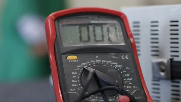
Reading the Display
You can also use the digital multimeter display to confirm your test results. Here is what you might see:
- Zero resistance or a value close to zero means the circuit is complete.
- Infinite resistance or the word "Open" shows there is a break in the circuit.
- When you test a switch, a beep and zero reading mean the switch works when turned on. Infinite resistance means the switch is off or faulty.
You can use the table below to help you understand the results:
| Result Type | Indicator | Description |
|---|---|---|
| Pass | LED lights up / Buzzer sounds | The circuit is complete and functioning properly. |
| Fail | LED remains OFF / Buzzer silent | There is a break in the circuit, so continuity is absent. |
Using the Results
You can use your continuity test results to diagnose electrical problems. A beep or near-zero resistance tells you the circuit is intact. No beep or a high resistance reading points to a break, loose connection, or damaged wire. This method helps you find faults quickly and keeps your devices running smoothly. You can check fuses, switches, and wires to make sure each part works as it should. The continuity test symbol on your multimeter makes this process simple and reliable.
Troubleshooting Continuity Test Issues
Common Mistakes
When you perform a continuity test, you may run into a few common mistakes. These errors can lead to false results or even damage your equipment. You can avoid these problems by following some simple steps:
- Always remove power from the circuit before you start the test. This step keeps you safe and prevents damage to your multimeter.
- Discharge any capacitors in the circuit before you check for continuity. Charged capacitors can give you false readings or harm your meter.
- For multi-core cables, label both ends and test one conductor at a time. This method helps you avoid confusion and ensures you do not miss any broken connections.
- Use the probe tips or alligator clips that come with your meter to keep your hands steady during the test. A steady connection gives you more accurate results and helps you spot bad connections.
- If you test circuits with diodes or other semiconductors, remember that they may show continuity in only one direction. Switch to diode test mode if you need to check these components.
You can prevent most mistakes by preparing your tools and understanding the circuit before you begin. Careful setup leads to better troubleshooting and fewer surprises.
Fixing False Readings
Sometimes, you may get a false reading during a continuity test. You can follow these steps to solve the problem:
- Shut off power to the unit at the main disconnect before you start the test.
- Use your meter to verify that no power is present in the electrical cabinet.
- Manually push in the contactor to simulate normal operation and test the circuit under real conditions.
- Set your meter to the ohms setting and check continuity across each leg of the contactor.
- Compare your readings. They should be very low, usually less than 1 ohm, and consistent across all legs.
You may also see false positives or negatives because of environmental factors like humidity, which can affect resistance readings. Equipment calibration issues can also cause inaccurate results. Inadequate testing methods may lead you to misinterpret the results of your test. Always check your equipment and environment before you trust your test results.
Tip: If you keep getting unexpected results, clean your probe tips and check your meter’s calibration. Reliable tools help you find faults and avoid confusion during your test.
By following these steps, you can improve your continuity test process and quickly find issues like bad connections or broken connections. This approach makes troubleshooting easier and keeps your electrical systems running smoothly.
You now know how to spot the continuity test symbol and use it for quick circuit checks. Always power off circuits before testing to stay safe. Practicing continuity testing helps you find open circuits and broken connections faster. A multimeter makes it easy to check if electricity can flow between components. For more skills, explore these helpful guides:
Keep learning and practicing to improve your troubleshooting skills in electronics.
FAQ
What does the continuity test symbol look like?
You usually see a symbol that looks like sound waves, a speaker, or a sideways Wi-Fi icon. This symbol helps you find the continuity mode on your multimeter quickly.
Can I use the continuity test to check conductivity?
Yes, you can. The continuity test checks if electricity flows through a path. If the circuit has good conductivity, your multimeter will beep or show a low resistance value.
Why should I turn off power before testing continuity?
You must turn off power to stay safe. Testing a live circuit can damage your multimeter and may cause electric shock. Always disconnect power before you start.
What does it mean if my multimeter does not beep during a continuity test?
If you do not hear a beep, the circuit is open or broken. This means electricity cannot flow between the two points you are testing.
Can I test switches and fuses with the continuity function?
Yes. Place the probes on both ends of the switch or fuse. If you hear a beep, the part works. No beep means the switch or fuse is faulty.


