Never Fear Dead Circuits Continuity Testing on a Multimeter
Continuity means you have a complete, unbroken electrical path. This concept of continuity is vital for any circuit to funct
Continuity means you have a complete, unbroken electrical path. This concept of continuity is vital for any circuit to function correctly.
Imagine a clear road where traffic flows freely. A circuit with good continuity works just like that. A lack of continuity is like a road with a washed-out bridge, often caused by broken wires or loose connections. This stops all flow.
Continuity testing is your first step in troubleshooting. This essential testing with a multimeter confirms if a path is complete. Performing continuity testing on a multimeter helps you find the exact problem, taking the guesswork out of troubleshooting.
Key Takeaways
- Continuity testing checks if an electrical path is complete. This test helps you find broken wires or bad connections.
- Always turn off the power to a circuit before you test it. This keeps you safe and protects your tools.
- Use your multimeter's continuity setting. It usually makes a beep sound if the path is good.
- A beep means good continuity, like a clear road. Silence means a broken path, like a road with a missing bridge.
- You can test wires, fuses, and switches with this method. It helps you fix many electrical problems.
What is Continuity?
You already know that continuity means an unbroken path. Now, let's explore what that means for an electrical circuit and why this concept is so important for all your diagnostic testing.
The Concept of a Complete Circuit
A circuit needs a complete, closed loop for electricity to work. This is the core principle of electrical continuity. A closed circuit provides a continuous path for electric current to flow. The electricity circulates from the power source, moves through all the components, and returns to the source. This complete journey is what we call continuity.
Think of it like a circle. If the circle has any gaps, it is incomplete. A circuit with good continuity is a perfect, unbroken circle. Without this complete path, the flow of electrons stops. Your device will not function. The presence of continuity confirms the path is whole and ready for action.
An operational switch that is turned ON shows perfect continuity. A blown fuse, however, breaks the path and has no continuity. This simple idea of a complete path is the foundation of all electrical testing.
Why This Test is a First Step
Troubleshooting can feel complex, but continuity testing gives you a simple starting point. It is the first and most essential diagnostic procedure because it quickly answers one basic question: is the path for electricity open or closed? This initial testing saves you valuable time.
This quick testing can prevent larger failures during maintenance and repair. Before you check complex components, you perform continuity testing to confirm the basics are working. This process helps you:
- Check wires and cables for hidden breaks.
- Test fuses to see if they have blown.
- Verify that switches and relays are working correctly.
- Diagnose faults in more complex circuits.
This fundamental testing is crucial for both professionals and hobbyists. It confirms the integrity of your connections, making it a powerful first step in any electrical diagnosis. The simple confirmation of continuity builds a strong foundation for all further testing.
Performing Continuity Testing on a Multimeter
You have learned the "what" and "why" of continuity. Now, let's move to the "how." This step-by-step guide will give you the confidence to perform continuity testing on a multimeter safely and effectively. You are now ready to turn theory into practice.
Setting Up Your Multimeter
Your first task is to prepare your tool. Setting up your multimeter correctly is essential for accurate continuity testing. The process is simple and quick.
- Find the Continuity Setting: Look for a symbol on your multimeter dial that looks like a sound wave or a diode (a triangle with a line). This setting activates the continuity testing function.
- Turn the Dial: Rotate the main dial on your multimeter to align with this continuity symbol. Your multimeter is now ready for testing continuity.
- Test Your Probes: Before testing your circuit, touch the metal tips of your red and black probes together. You should hear a beep. This confirms your multimeter and its leads are working correctly. This simple action ensures you can trust your testing results.
Pro Tip: The beep for continuity is not always the same. The multimeter sends a tiny amount of electricity to check the path. It beeps if the resistance is low enough. Different multimeter models have different thresholds for this.
Multimeter Model Continuity Threshold Fluke 177 Beeps at <25 Ω Brymen BM235 Between 30 Ω and 480 Ω Unspecified (manual interpretation) Below 50Ω (audible indication above 50Ω)
Knowing this helps you understand why some connections might show continuity on one multimeter but not another.
The Golden Rule: Power OFF!
This is the most important rule of continuity testing. You must follow it without exception to protect yourself and your equipment.
⚠️ DANGER: ALWAYS DISCONNECT POWER Never perform continuity testing on a circuit that has power. Testing a live circuit can destroy your multimeter. More importantly, it creates a severe risk of electric shock.
You must unplug the device from the wall. You should also remove any batteries. Some circuits, especially on a PCB, use capacitors to store energy. These components can hold a dangerous electrical charge even when the device is unplugged. You must safely discharge capacitors on a PCB before testing continuity. This risk is real, as capacitors can release stored energy and cause harm. Always assume a circuit on a PCB might have stored energy. Checking a PCB for power is a critical safety step before any testing. This rule is non-negotiable for safe and accurate continuity testing.
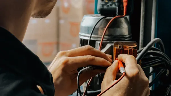
The Two-Probe Test Method
With your multimeter set up and the circuit powered down, you can begin the actual testing. The two-probe method is the standard procedure for testing continuity. This method confirms an unbroken electrical path. Your multimeter applies a small voltage across the two probes. If the path is complete, current flows, and the multimeter signals continuity with a beep. This is how you check for continuity on wires, fuses, and traces on a PCB.
Here is the correct procedure for testing a simple wire for continuity:
- Set your multimeter to the continuity setting, as described above.
- Perform the preliminary check by touching the probes together to hear the beep.
- Connect one multimeter probe firmly to one end of the wire you wish to test.
- Touch the other multimeter probe to the other end of the same wire.
If you hear a continuous beep, you have good continuity. The electrical path is complete. If the multimeter remains silent, the path is broken. This simple testing process is powerful. You can use it to check connections on a project PCB, test a switch, or find a break in a cable. This fundamental skill in continuity testing on a multimeter is your key to diagnosing countless electrical issues on any PCB. You can confidently test any dead circuit on a PCB, from a simple toy to a complex appliance PCB, by following these steps. This testing method is your first step to becoming a master of troubleshooting a PCB.
Real-World Applications
You can apply your knowledge of continuity testing to many real-world problems. This skill is useful for simple home repairs and complex professional diagnostics. Your multimeter is the key to solving these electrical puzzles. This section shows you how to use continuity testing for troubleshooting in different situations.
Basic Wire and Fuse Testing
You can start with simple tasks around the house. An appliance cord that stops working often has a broken wire inside. You can easily check this with your multimeter. Testing a fuse is another common task. A fuse protects circuits from too much current. When it blows, it breaks the electrical path.
Here is how you perform continuity testing on a standard fuse:
- Turn your multimeter dial to the continuity setting.
- Touch one probe to each metal end of the fuse.
- A beep from the multimeter means you have continuity, and the fuse is good.
- Silence means the fuse is blown and has no continuity. You must replace it.
This simple testing saves you from guessing if a part is faulty.
Checking Switches and Connections
Switches and connectors are frequent points of failure. A switch is designed to open and close a circuit factors. You can test its function easily. With the switch disconnected, test for continuity in the OFF position. Your multimeter should be silent. Then, flip the switch to the ON position. The multimeter should beep, showing good continuity.
Connections can fail for many reasons. Your multimeter helps you find these issues. Common problems that break continuity include:
- Loose Terminals: Wires that are not crimped or seated correctly.
- Corrosion: Buildup that creates high resistance and poor continuity.
- Damaged Wires: Breaks near a connector that cause intermittent faults.
Finding these issues is a major step in any electrical troubleshooting.
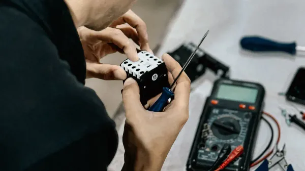
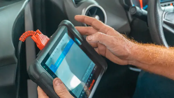
Advanced PCB Continuity Testing
In professional settings, PCB continuity testing is essential for quality. Technicians use continuity testing on a multimeter to diagnose complex systems. For example, they check automotive wiring harnesses for breaks. A reading near 0 ohms confirms good continuity in a wire. A high reading points to a problem. This testing ensures vehicle reliability. For a PCB, this testing is vital.
For professionals, PCBA continuity testing is a core part of quality control. At a company like Nova Technology Company (HK) Limited, a HiSilicon-designated (authorized) solutions partner, this skill is critical. Engineers perform detailed PCB continuity testing to verify every trace on a new PCB. This PCBA continuity testing ensures there are no shorts or open circuits before a PCB is assembled. This level of testing continuity guarantees the quality and function of the final product. PCBA continuity testing on a PCB is a non-negotiable step. This PCBA continuity testing confirms the integrity of the PCB. Advanced PCB continuity testing is also used to repair a damaged PCB. Technicians use PCB continuity testing to find broken traces on a PCB. This precise PCB continuity testing allows for targeted repairs. PCBA continuity testing is how they ensure a PCB works perfectly. This PCBA continuity testing on a PCB is a mark of high-quality manufacturing. This PCB continuity testing validates the entire PCB design.
Interpreting Multimeter Results
You have performed the test. Now you need to understand the results. Your multimeter gives you clear signals. Learning to interpret continuity test results is the final step in your diagnosis. This skill helps you pinpoint the exact problem. You can confidently interpret continuity test results with a little practice.
Good Continuity: The Beep
The most satisfying sound in electrical troubleshooting is the beep from your multimeter. This audible signal tells you that you have good continuity.
Your multimeter produces a beep when it detects a complete path for current to flow. The beep confirms that the electrical resistance in the circuit is below a certain level. This level is often below 50 ohms, but it does not mean the resistance is zero. The beep is a quick audio confirmation of a closed circuit. This is especially useful when you cannot easily see the multimeter's screen while testing.
What is a "Good" Reading? 💡 For most simple wires, you want the resistance to be as close to 0 ohms (Ω) as possible. However, professional standards provide more specific guidelines. For high-reliability electronics, the IPC standard suggests a continuity specification of 2 ohms or less. This ensures a strong, reliable connection. A reading this low confirms excellent continuity.
Open Circuit: The Silence
Silence from your multimeter during a continuity test is just as informative as a beep. It tells you there is a problem. A silent multimeter means you have an "open circuit." The electrical path is broken, and current cannot flow.
When your multimeter detects an open circuit, its display will often show OL. This stands for "Overload" or "Open Loop." Some multimeter models might display a 1 instead. This OL reading, combined with the silence, is a definite sign of no continuity.
An open circuit can happen for many reasons. The break could be obvious or hidden inside a component or wire. Common causes include:
- Mechanical Stress: Bending or vibration can fracture solder joints or crack thin copper traces on a circuit board.
- Thermal Damage: Too much heat from a failing component can cause connections to lift or burn away.
- Electrical Overload: A sudden surge of high current can vaporize a section of a wire or trace, creating a gap.
- Chemical Corrosion: Exposure to moisture or leftover chemicals from manufacturing can eat away at metal contacts over time.
- Manufacturing Defects: Poor soldering or weak connections can fail unexpectedly.
This testing helps you find these invisible breaks.
Understanding Resistance Readings
Sometimes, your continuity test results are not a simple beep or silence. You might see a resistance value on your multimeter's screen without a beep. This is where accurate continuity testing becomes a more detailed investigation. These readings give you important clues about the circuit's health.
Some components are designed to have resistance. They will show a specific ohm value while still having continuity. This is normal for parts like:
- Resistors: Their job is to resist current, so they will show their rated resistance value.
- Relay Coils: These electromagnetic coils will show resistance.
- Transformers: The wire windings inside a transformer have inherent resistance.
- Compressor Windings: Motor windings in compressors have specific ohm ratings.
For these parts, you are checking if the resistance value is correct, not just looking for a 0 ohm reading. A reading of OL would still indicate a break.
Other times, an unexpected resistance reading points to a problem. A partial or fluctuating connection can cause this. The table below helps you understand these intermediate results.
| Multimeter Display | Meaning | What to Do Next |
|---|---|---|
| A steady, low value (e.g., 50-500 Ω) | Partial continuity. | The connection is weak. Investigate for corroded contacts, a frayed wire, or a failing component. |
| A fluctuating value | Unstable connection. | The connection is intermittent. Wiggle the wires and connectors during testing to find the loose spot. |
This level of analysis is key for advanced troubleshooting. It moves beyond simple continuity testing on a multimeter and into diagnosing complex electrical issues.
You now have a powerful skill in your diagnostic toolkit. Continuity testing is a simple, safe, and effective method to verify electrical paths. Mastering this core skill boosts your confidence and removes the guesswork from troubleshooting. You can quickly find breaks in wires, check fuses, and confirm connections.
With this knowledge, you no longer need to fear dead circuits. You can now confidently diagnose and solve a wide range of common electrical problems, turning frustration into accomplishment.
FAQ
Can I test a PCB with this method?
Yes, you can. Continuity testing is perfect for checking a printed circuit board (PCB). You can find broken traces on a PCB. This test confirms the electrical paths on the PCB are complete. It is a key step for checking the quality of any PCB.
What if my multimeter shows a number but does not beep?
This often means there is some resistance. The connection is not perfect, but a path exists. A low number indicates decent continuity. This reading can help you judge the quality of a connection on a PCB. A high number on a PCB trace suggests a problem.
Why is my reading not exactly 0 ohms?
A perfect 0 ohm reading is rare. Your test leads have their own small resistance. A reading below 1 or 2 ohms shows excellent continuity. This low reading confirms a high-quality connection on your PCB. The goal is a very low number, not always zero.
Can I damage a PCB during continuity testing?
You can damage your PCB if it has power. Always disconnect all power sources. This includes batteries. Testing a live PCB can destroy its components. A powered PCB test also risks damaging your multimeter. Proper setup ensures the safety and quality of your PCB repair.