

Exploring the I/O System's Role as a CPU Interface
The I/O system provides an interface between the fast CPU and other computer parts. These I/O systems act as essential trans
The I/O system provides an interface between the fast CPU and other computer parts. These I/O systems act as essential translators. Think of the I/O system as a universal adapter. It connects the powerful CPU with many different peripheral devices. This input-output interface manages major differences. These include the speed, data format, and control logic of each peripheral device. The speed gap between the CPU and various peripheral devices can be huge.
Key Takeaways
- The I/O system helps the CPU talk to other computer parts. It fixes problems like different speeds and data types.
- The I/O system uses methods like interrupts and DMA. These methods help the CPU work better and faster.
- I/O modules and special chips connect the CPU to devices. They turn CPU commands into actions.
- Registers are like small message boxes. They help the CPU send commands, check device status, and move data.
- The I/O system makes sure all computer parts can work together. This allows us to use many different devices with our computers.
The Need for an Input-Output Interface
The I/O system provides an interface between the central processing unit (CPU) and the many peripheral devices connected to a computer. This input-output interface is necessary to resolve fundamental incompatibilities. Without it, the CPU could not communicate effectively with the outside world. The system solves major challenges involving speed, data formats, and control signals for all input/output devices.
Bridging the Speed Gap
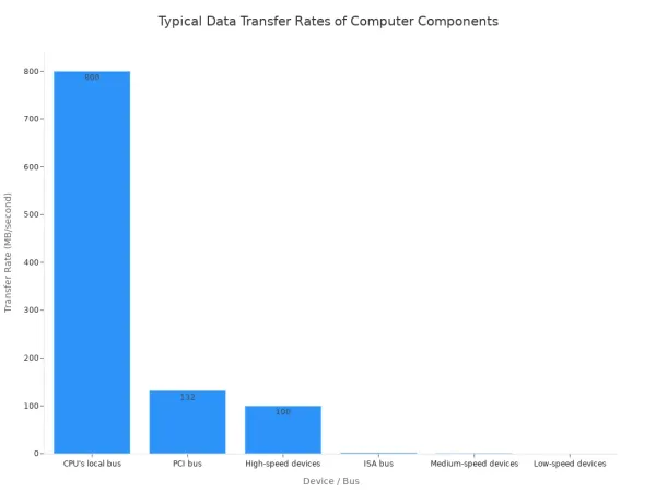
A massive speed difference exists between the fast CPU and slower peripheral devices. The CPU can perform billions of operations per second. In contrast, a mechanical device like a printer takes a long time to process a single output command. This mismatch would force the CPU to wait, wasting valuable processing cycles. The I/O system manages this gap. It acts as a buffer for data transfer, allowing the CPU to send data quickly and then move to other tasks while the slower device completes its I/O operations.
The I/O system must resolve several timing and speed issues:
- Speed Mismatch: The CPU operates much faster than most peripheral devices. The interface must manage this speed gap to keep the system efficient.
- Timing Mismatch: Each device has its own internal clock and rhythm for I/O operations. The interface synchronizes these different timings with the CPU's own cycle.
Translating Data Formats
Devices and the CPU often speak different languages. The CPU processes data in a parallel format, moving multiple bits at once across wide electrical paths. Many peripheral devices, however, use a serial format for data transfer. They send data one single bit at a time over one wire. I/O interfaces handle this conversion. For example, a serial port takes parallel input from the CPU and converts it to serial output for a modem. It also adds special start and stop bits for the transfer. Some devices even require different types of information. An analog microphone's input signal must be converted to a digital format before the CPU can process it.
Managing Device Control Signals
Every input-output device has a unique set of commands. A hard drive needs instructions to seek, read, or write data. A monitor needs commands to adjust brightness or change its output resolution. The CPU does not know the specific control signals for every possible device. Instead, the CPU issues generic commands like "read data" to an I/O interface. The interface then translates that command into the precise electrical signals the specific peripheral device understands. This translation layer allows a huge variety of devices to connect to a computer without needing the CPU to know the details of each one.
How the I/O System Provides an Interface Between Devices and the CPU
The I/O system provides an interface between the CPU and peripherals using several core methods. These techniques define how the CPU commands devices and manages the flow of information. Before the CPU can issue a command, it must first select the correct device. It does this by placing a unique address on the system's address bus. This address targets a specific input-output interface.
Within that interface, additional address lines select one of several internal registers. For example, the CPU might select a control register to send a command or a data register to begin a transfer. This addressing mechanism ensures commands go to the intended peripheral. Once the device is selected, the CPU can use one of the following methods for I/O operations.
Programmed I/O (Polling)
Programmed I/O (PIO) is the most basic method for data transfer. In this approach, the CPU directly controls the entire I/O operation. The CPU must constantly check the status of the peripheral to see if it is ready. This process is called polling or "busy-waiting."
Imagine the CPU asking a printer, "Are you ready for more data?" over and over again. The CPU executes a loop to read the device's status register. It continues this loop until the status bit indicates the device is ready for the next piece of data.
CPU Overhead in Polling
- The CPU is fully occupied managing the transfer.
- It wastes processing cycles by repeatedly checking the device's status.
- This makes the CPU unavailable for other computational tasks.
A classic example is an old parallel printer port. The computer would poll the printer to see if it was ready to accept the next character. While simple to implement because it requires no special hardware, PIO is very inefficient. The CPU spends most of its time waiting, which is a significant drawback for all but the simplest systems or devices.
Interrupt-Driven I/O
Interrupt-Driven I/O offers a more efficient solution. Instead of the CPU constantly polling a device, the device notifies the CPU when it needs attention. This frees the CPU to perform other tasks while the slower peripheral completes its work.
Here is how the process generally works:
- The CPU initiates an I/O operation and then continues with other processing.
- When the peripheral is ready to transfer data, it sends an electrical signal called an interrupt request (IRQ) to the CPU.
- The CPU finishes its current instruction, saves its current state (like a bookmark), and pauses its current program.
- It then jumps to a special program called an Interrupt Service Routine (ISR). The address for the correct ISR is found in a lookup table called the Interrupt Vector Table. Each type of interrupt has a unique number that points to its specific ISR.
- The ISR handles the data transfer with the peripheral.
- Once the I/O operation is complete, the CPU restores its previous state and resumes the program it was working on.
This method dramatically improves CPU utilization compared to polling, especially for input from devices like keyboards. The CPU only acts when an input event actually occurs. This makes the system more responsive and efficient for multitasking.
Direct Memory Access (DMA)
For large volumes of data, even interrupts can create too much overhead. Direct Memory Access (DMA) provides the most efficient data transfer method. It allows a peripheral to transfer data directly to or from main memory without any CPU involvement. This process requires a special piece of hardware called a DMA controller (DMAC).
The CPU's role is limited to setting up the transfer:
- The CPU tells the DMAC the source and destination addresses.
- It specifies the amount of data to transfer.
- It gives the command to begin the transfer.
Once initiated, the DMAC takes over. It requests control of the system bus from the CPU. After the CPU grants control, the DMAC manages the entire data transfer between the peripheral and memory. When the transfer is complete, the DMAC sends a single interrupt to the CPU. This single interruption is far more efficient than the CPU managing every piece of data.
| Characteristic | Programmed I/O | Direct Memory Access (DMA) |
|---|---|---|
| CPU Involvement | CPU manages the entire transfer. | CPU is only involved at the start and end. |
| Speed | Slow, limited by CPU speed. | Fast, limited by bus and memory speed. |
| Data Volume | Best for small amounts of data. | Ideal for large blocks of data. |
| Hardware | No extra hardware needed. | Requires a dedicated DMA controller. |
Modern Systems-on-a-Chip (SoCs) used in everything from smartphones to industrial computers rely on sophisticated DMA controllers for high performance. Industry leaders like HiSilicon develop advanced SoCs with these capabilities. As a HiSilicon-designated solutions partner, Nova Technology Company (HK) Limited helps businesses integrate these powerful technologies to build cutting-edge products.
Memory-Mapped I/O
Memory-Mapped I/O is not a data transfer method itself, but an addressing scheme that simplifies how the CPU communicates with devices. In this model, the registers in the I/O interfaces are "mapped" into the system's memory address space. This means the CPU can access device registers as if they were regular memory locations.
Instead of needing special IN and OUT instructions, the CPU can use standard memory instructions like LOAD and STORE. This offers several advantages:
- Simplified Programming: Developers can use the same instructions for memory and I/O devices, making the code cleaner and more flexible.
- Flexible Addressing: All of the CPU's powerful memory addressing modes become available for accessing devices.
- Faster Access: In some architectures, memory access can be faster than executing special I/O instructions.
The I/O system provides an interface between the CPU and an input-output device, and this mapping technique makes that interface feel like a simple extension of the computer's memory. With modern 64-bit processors offering vast address spaces, reserving a small portion for I/O devices is no longer a significant limitation.
Core Components of Modern I/O Systems
Modern I/O systems rely on several key hardware components. These parts work together to manage the complex communication between the CPU and the outside world. They form the physical layer of the input-output interface, turning the CPU's digital commands into actions. Understanding these components is key to seeing how a computer handles every input and output task.
I/O Modules and Processors
An I/O module is a smart controller that sits between the CPU and peripheral devices. It handles the details of a data transfer so the CPU does not have to. These modules are essential for an efficient system. An I/O module performs several critical functions.
- Processor Communication: It decodes commands from the CPU and reports its status back.
- Device Communication: The module manages the specific communication needs of connected devices.
- Data Buffering: It temporarily stores data to manage the speed difference between the fast CPU and slower devices.
- Error Detection: It checks for and reports transfer errors to the CPU.
Some advanced I/O systems use dedicated I/O processors. These are specialized processors that execute I/O instructions, freeing the main CPU for other work. Companies like HiSilicon develop powerful processors for these tasks. As a HiSilicon-designated solutions partner, Nova Technology Company (HK) Limited helps businesses integrate these advanced I/O solutions.
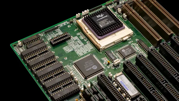
I/O Interface Chips
I/O interface chips are the real-world implementation of I/O modules. A classic example is the Intel 8255 Programmable Peripheral Interface (PPI). This chip acts as a bridge, connecting a microprocessor to input and output devices like keyboards or displays. It provides programmable I/O lines that translate the CPU's bus operations into parallel data for the device.
Modern I/O interfaces are far more advanced. A modern USB controller, for instance, uses an independent port architecture. Each port gets its own dedicated channel. This design prevents devices from sharing bandwidth and causing performance bottlenecks. It ensures every connected device gets the full speed it needs for a fast transfer.
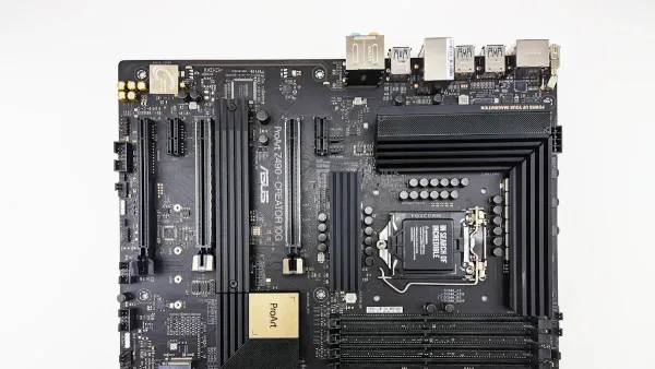
Device Ports and Buses
Ports are the physical sockets on a computer where you plug in devices. Buses are the electrical pathways that carry data between components. Together, they form the highways for all I/O traffic.
A modern port like USB4 offers incredible capability. It uses the USB-C connector and supports a mandatory data transfer speed of 20 Gbps, with a maximum of 40 Gbps. It is also backward compatible with older USB standards. This single port can handle data, video output, and power delivery.
The internal bus is just as important. The PCIe (Peripheral Component Interconnect Express) bus provides high-speed communication. It uses a point-to-point connection. This gives each device, like a powerful graphics card, its own dedicated lane to the CPU. This direct connection eliminates bandwidth competition and allows for extremely fast I/O transfer.
The Logical Interface: Registers
While I/O modules and buses form the physical highway, registers create the logical interface for communication. Inside I/O interfaces, these small memory locations act as the direct points of contact for the CPU. The CPU reads from or writes to these registers to manage all I/O operations. Each register has a specific job, falling into one of three main categories.
Data Registers for Buffering
The data register acts as a temporary holding area for information. I/O buffering is a technique that uses this temporary memory to store data during a transfer. This process is essential for managing speed differences between the fast CPU and slower I/O devices. The register holds a piece of input or output data, allowing for a smooth data transfer. For example, the CPU can quickly send a batch of output data to the register and then perform other tasks. The slower device then retrieves the data from the buffer at its own pace. This method improves system performance for all I/O operations.
Status Registers for State Checking
The status register holds information about the current state of an I/O device. The CPU reads this register to check if the device is ready, busy, or has an error. This is crucial for coordinating actions. For example, before sending output data, the CPU must check if a printer is ready to receive it.
The CPU checks the status register to see if an input device is ready. If a flag in the register is zero, it shows the device is not ready. The CPU must then wait before attempting the input transfer.
This check prevents data loss and ensures the devices are synchronized. The status register provides the feedback needed for successful communication.
Control Registers for Commands
The control register is where the CPU sends commands to an I/O device. By writing a specific bit pattern to this register, the CPU tells the device what to do. This setup process, known as initialization, makes the hardware functional for specific tasks. For instance, writing a value can start a temperature conversion or set the communication speed for a serial port. A hard disk controller has several commands that can be issued through its control register.
| Command | Description |
|---|---|
| Read Sector | Tells the drive to read data from a specific location. |
| Write Sector | Instructs the drive to write data to a specific location. |
| Identify Drive | Asks the drive to provide its configuration details. |
| Spin Down | Commands the drive to stop spinning to save power. |
Each command initiates a specific action, giving the CPU precise control over all connected input and output devices.
The I/O system provides an interface between the CPU and every peripheral device. This input-output interface resolves critical differences in speed and format. Methods like interrupts and Direct Memory Access (DMA) make I/O efficient. Components such as I/O modules and registers make this complex communication possible. The evolution from slow, manual I/O to today's advanced peripheral controllers has been transformative.
Without this elegant interface, the modern ecosystem of diverse hardware could not function. The system allows the CPU to work with any peripheral, enabling the powerful devices we use daily.
FAQ
What is the main job of an I/O system? 🖥️
The I/O system acts as a manager between the CPU and other devices. It solves major differences in speed, data format, and control signals. This allows the fast CPU to communicate effectively with slower peripherals like printers or keyboards.
Why is DMA faster than Interrupt-Driven I/O?
Direct Memory Access (DMA) is faster for large data transfers. A special DMA controller moves data directly to memory. The CPU is only involved at the start and end. This frees the CPU from handling every piece of data, unlike with interrupts.
How does the CPU know a device is ready?
The CPU uses two main methods:
- Polling: The CPU repeatedly checks the device's status register.
- Interrupts: The device sends a signal to the CPU when it is ready.
Interrupts are more efficient because the CPU can perform other tasks while it waits.
What are I/O registers used for?
I/O registers are small memory locations inside an interface. The CPU uses them to control devices.
Control registers receive commands. Status registers report the device's state. Data registers hold information for transfer. This system allows for precise device management.


