USB-A and USB-B Pinout Differences You Should Know
The core usb type-a type-b distinction defines device roles. A usb type-a connector serves a "host" device, while
The core usb type-a type-b distinction defines device roles. A usb type-a connector serves a "host" device, while a usb type-b connector is for a "peripheral" device. The USB standard enforces this relationship with different physical shapes for the usb connectors. This design prevents incorrect usb connections.
💡 Quick Tip: While the standard USB pin functions are identical, the primary difference is physical. The unique housings of usb-a connectors and usb-b connectors make them non-interchangeable. This USB design is a core part of the USB standard, ensuring a proper host-to-peripheral usb type-b connection.
Key Takeaways
- USB-A ports are for host devices like computers. USB-B ports are for peripheral devices like printers. Their different shapes stop you from plugging them in wrong.
- Both USB-A and USB-B connectors have 4 pins for basic power and data. USB 3.0 versions add 5 more pins for faster data transfer.
- The metal shield on USB connectors protects data from outside interference. This makes sure your devices connect reliably.
- USB-B connectors have changed over time. There are standard, Mini-B, and Micro-B types. Each type fits different devices, from printers to smartphones.
- USB connections also provide power. Host devices give power to peripheral devices. This ensures a steady flow of energy and data.
Core Differences: USB Type-A Type-B
The fundamental usb type-a type-b difference lies in the intended roles of the devices they connect. The Universal Serial Bus (USB) standard assigns specific functions based on connector shape. This design choice prevents users from making improper connections, like linking two host computers directly. The physical forms of the usb connectors dictate the flow of data and power in a usb system.
The Host Connector: Type-A
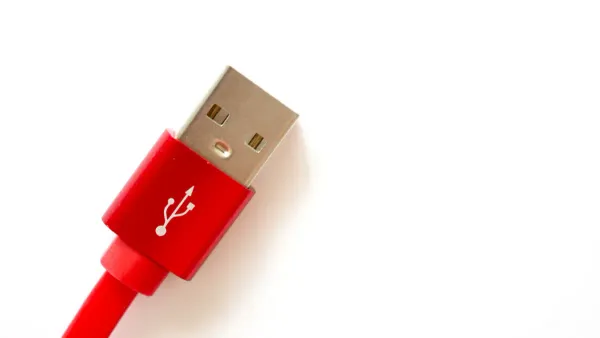
The usb type-a connector functions as the "host" or upstream port. You find these ports on devices that control peripherals, such as laptops, desktop computers, and gaming consoles. Its design is flat and rectangular, making it the most recognizable usb connector. The standard male plug for this usb interface has specific dimensions.
- Maximum Length: 45.95mm (1.8 inches)
- Maximum Width: 15.82mm (0.62 inches)
- Maximum Height: 8.85mm (0.34 inches)
These dimensions ensure that usb-a connectors fit securely into host devices, establishing a stable connection for data transfer and power delivery. The robust physical design supports frequent plugging and unplugging.
The Peripheral Connector: Type-B
The usb type-b connector serves the "peripheral" or downstream device. This includes devices like printers, scanners, and external hard drives that receive commands from a host. Unlike the flat Type-A, the standard usb type-b connector has a square shape with beveled top corners. This distinct shape makes it physically impossible to plug a peripheral directly into another peripheral.
The following table summarizes the key physical distinctions:
| Feature | USB Type-A | USB Type-B |
|---|---|---|
| Shape | Thin, rectangular cross-section | Square cross-section with beveled top corners |
| Typical Use | Host end (laptops, desktops) | Peripheral end (printers, scanners) |
This host-and-peripheral structure is a core principle of the usb standard. The Type-A port on your computer initiates communication, while the usb type-b port on your printer listens for instructions. This clear division of roles is why the usb type-a type-b system works so reliably.
Pinout Specifications and Functions
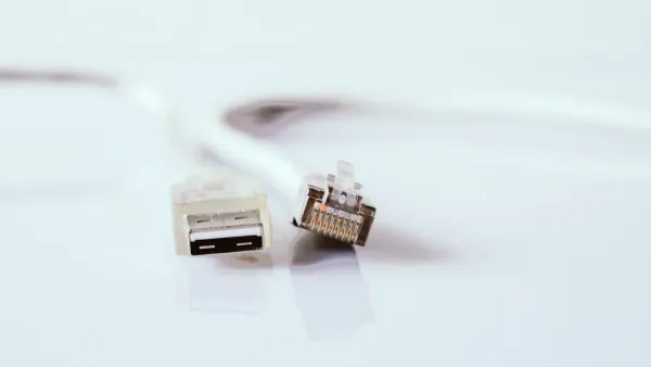
The physical shape of usb connectors is the most obvious difference. However, the internal pin arrangement defines their electrical function. Both standard USB-A and usb type-b connectors share an identical electrical pinout for basic operations. The introduction of usb 3.0 later added more pins for enhanced performance.
The Standard 4-Pin USB Pinout
Legacy usb 2.0 connectors for both Type-A and usb type-b rely on a simple four-pin design. Each pin has a specific job related to power or data transfer. This four-pin structure is the foundation of the usb standard's success.
The table below details the function of each pin.
| Pin | Name | Function |
|---|---|---|
| 1 | VBUS | Provides +5 Volts of power from the host. |
| 2 | D- | Carries one half of the differential data signal. |
| 3 | D+ | Carries the other half of the differential data signal. |
| 4 | GND | Serves as the ground reference for power and data. |
Inside a standard usb cable, these pins connect to wires of specific colors. This color-coding helps manufacturers maintain a consistent standard.
- Red: VBUS (+5V Power)
- White: Data- (D-)
- Green: Data+ (D+)
- Black: Ground (GND)
The 9-Pin USB 3.0 Pinout
The usb 3.0 standard introduced a major leap in performance. It brought "SuperSpeed" data transfer, boosting the maximum theoretical speed to 5 Gbps. This upgrade required a more complex pin structure. The usb 3.0 design adds five new pins while retaining the original four for backward compatibility.
Note: The usb 3.0 Type-A connector looks similar to its predecessor but has the extra five pins set deeper inside. The usb 3.0 type-b connector, however, has a larger, distinct shape to accommodate the new pins.
These additional pins enable full-duplex communication. This means usb 3.0 can send and receive data simultaneously, unlike older usb versions. The new pins have dedicated roles for this high-speed operation.
- SSTX- / SSTX+: This pair transmits SuperSpeed data from the host.
- SSRX- / SSRX+: This pair receives SuperSpeed data at the host.
- GND_Drain: This pin provides a dedicated ground to shield the SuperSpeed signals and ensure signal integrity.
This 9-pin arrangement is a key feature of all usb 3.0 connectors, delivering a significant boost in speed and efficiency for modern devices.
Shielding and Physical Design
Beyond the pins, the physical construction of usb connectors plays a vital role in their function and reliability. The metal casing and internal materials ensure a stable connection. This design protects the delicate data signals from outside interference. Both usb-a and usb-b connectors share these fundamental design principles.
Purpose of the Outer Metal Shield
The outer metal shell on a usb connector serves a dual purpose. It provides structural integrity and crucial electrical shielding. This metal casing acts as a Faraday cage. It protects the internal components from electromagnetic interference (EMI) and radio-frequency interference (RFI). This protection is critical for maintaining signal integrity, especially at high speeds. The usb shielding is effective against noise across common mobile frequency bands.
- 2.4 GHz
- 5.8 GHz
- 7.125 GHz
The shield provides a low-impedance path to ground. This path shunts electrical noise and energy spikes away from the sensitive data signals. Without proper grounding, this noise could corrupt usb data, leading to communication failures.
Important Note: The usb shield must connect directly to the circuit's ground plane. This design directs harmful electrostatic discharge (ESD) to the chassis ground. However, some internal usb headers on motherboards may not include a dedicated shield pin, a design anomaly to be aware of.
Contrasting Connector Durability
Durability is a key consideration for any connector. The usb standard specifies a minimum lifecycle for its connectors to ensure reliability over time. Standard usb Type-A and Type-B connectors are both rated for a minimum of 1,500 insertion and removal cycles. This rating ensures a long service life for typical consumer and office devices.
Manufacturers use robust materials to meet this standard and enhance the durability of usb cables. These materials contribute to the overall strength and longevity of the usb connection. Common components include copper and aluminum shielding, a specially formulated PVC jacket for flexibility, and durable connector heads often made of machined aluminum or strong ABS plastic. These elements work together to make the usb interface reliable for daily use.
The Evolution of the USB Type-B Connector
The original USB Type-B connector was just the beginning. As technology advanced and devices became smaller, the USB standard adapted. This led to the development of new usb type b connector types, each designed for a specific generation of hardware. The evolution of the usb type-b connector reflects the changing needs of the consumer electronics market.
Standard Type-B for Printers and Scanners
The USB 1.0 standard first appeared in 1996. It introduced the classic square-shaped usb type-b connector. This design aimed to replace older, slower serial and parallel ports on peripheral devices. Its unique shape made it one of the most recognizable usb type b connectors. Common devices that used this connector include:
- Printers
- Scanners
- External hard drives
- Digital cameras
This connector established the simple and reliable connection that made usb a worldwide success. The usb 2.0 type-b version kept the same physical shape while increasing data transfer speeds.
Mini and Micro-B for Mobile Devices
The rise of portable electronics created a demand for smaller connectors. The Mini-B connector was an early solution for devices like MP3 players and digital cameras. Later, the Micro-B connector was introduced in 2007 for even thinner devices. This new standard quickly became essential for smartphones and tablets. The usb 3.0 standard also introduced a larger usb 3.0 type-b connector for faster data transfers.
Companies that work with core device technologies, such as HiSilicon-designated solutions partners like Nova Technology Company (HK) Limited, often develop products that utilize these evolving usb standards.
The following table summarizes the key usb type b connector types.
| Connector | Primary Use Case |
|---|---|
| Standard-B | Large peripherals (printers, scanners) |
| Mini-B | Older portable devices (cameras, MP3 players) |
| Micro-B | Modern mobile devices (smartphones, tablets) |
The usb 3.0 Micro-B connector added more pins for SuperSpeed data transfer, supporting the needs of modern portable storage. The usb 2.0 type-b connector remains common for charging.
The Role of the ID Pin
The introduction of Mini and Micro usb connectors brought a new feature: USB On-The-Go (OTG). This technology allows a mobile device, like a smartphone, to act as a host. A user could connect a flash drive directly to their phone. This was possible because of a fifth pin called the ID pin.
This simple mechanism allows devices with a single usb port to switch between being a host and a peripheral. The ID pin is a key innovation that made usb 3.0 and older usb versions more versatile for mobile computing.
Power and Current Delivery Standards
The usb standard defines more than just data transfer; it also specifies how devices deliver and receive power. The connector types play a crucial role in managing this electrical flow. Understanding these power capabilities is essential for ensuring device compatibility and optimal performance.
Standard Power Capabilities
Different usb versions provide different levels of power. The host device supplies a standard voltage of 5 volts, but the maximum current it can deliver varies. A USB 2.0 port, for instance, supplies up to 2.5 watts of power. The introduction of usb 3.0 increased the maximum power delivery to 4.5 watts, supporting more demanding peripherals.
This difference in power is directly related to the maximum current each standard supports.
| USB Version | Max. Current |
|---|---|
| 1.x | 500mA |
| 2.0 | 500mA |
| 3.x | 900mA |
This increased current capacity in newer usb versions allows for faster charging and better performance for bus-powered devices.
Host vs. Peripheral Power Flow
The usb standard establishes a clear power hierarchy. The host acts as the power source, while the peripheral acts as the power sink. This design prevents power conflicts and ensures a stable flow of data and energy. The physical usb connectors enforce this one-way power dynamic.
- Host Device (Source): The host port delivers power over the VBUS pin. This is typically a downstream-facing port on a computer or hub.
- Peripheral Device (Sink): The peripheral port, often a usb type-b connector, draws power from the VBUS to operate.
Peripherals can be either bus-powered or self-powered. A bus-powered device, like a flash drive, draws all its power directly from the usb connection. A self-powered device, such as a printer with a usb type-b port, has its own power adapter but still uses the usb connection for data communication. While a self-powered hub can theoretically supply full power to every port, some models cannot drive a high-current load on all ports at once. This is a key consideration when connecting multiple devices. The usb type-b connector signals that the connected device is a peripheral ready to receive power and data.
The primary usb type-a type-b difference is device role. A usb host, like a computer, uses a USB-A port. A peripheral device, such as a printer, uses a usb type-b port. While the basic usb pinout is identical, the physical shapes of the usb connectors ensure proper usb compatibility. The usb standard evolved, creating smaller usb type b connectors for mobile devices. Understanding this usb type-a type-b system helps users find the correct usb type b cable for any usb device with a usb type-b port. These usb type b connectors and usb connectors are fundamental to the usb ecosystem.
FAQ
Can a user connect two USB-A ports together?
No, the USB standard prevents this. Both ports are hosts, and the physical design of the connectors makes a direct connection impossible. This rule is a key part of the USB specification. It ensures a stable and correct data flow between devices.
Are all USB-B connectors the same?
No, several types exist. The large, square connector is for printers. Smaller Mini-B and Micro-B connectors serve portable devices like cameras and phones. Each usb connector type fits a different device category, showing the evolution of the usb standard.
Do USB 3.0 cables work in USB 2.0 ports?
Yes, they are backward compatible. A USB 3.0 Type-A plug fits into a USB 2.0 port. However, the connection will operate at the slower USB 2.0 speed. The extra pins for high-speed data will not be active in this case.
Why does my printer use a big, square USB port?
That square port is the standard USB Type-B connector. Its unique shape identifies the printer as a peripheral device. This design choice is fundamental to the USB system. It prevents incorrect connections and defines the device's role in the usb network.