Mastering Type A USB Pinout for Reliable Connections
You need to know the type a usb pinout if you want safe and reliable connections. When you understand how each usb type a pi
You need to know the type a usb pinout if you want safe and reliable connections. When you understand how each usb type a pin works, you avoid common mistakes and keep your devices compatible. Every usb type a connector has a specific design. You can spot the differences by looking at the usb contacts and the shape of the usb plug. This knowledge helps you choose the right usb type a cable or port every time. You can use this guide when you build, repair, or upgrade any usb device.
Key Takeaways
- Understanding the USB Type A pinout helps you make safe and reliable connections. Always check the pin layout before connecting devices.
- Each pin in a USB Type A connector has a specific function. Remember the color coding: red for power, white and green for data, and black for ground.
- USB Type A connectors are not reversible. Always check the orientation before inserting to avoid damage.
- USB 3.0 connectors have extra pins for faster data transfer. You can use USB 3.0 devices in USB 2.0 ports, but speeds will be limited to USB 2.0.
- Regularly inspect your USB cables and ports for damage. Clean them to ensure good connections and avoid data transfer issues.
Type A USB Pinout
Pin Layout
When you look at a usb type a plug, you see a row of metal contacts inside the connector. These contacts follow a standard layout, which helps you connect devices safely and reliably. The usb type a pinout shows you where each pin sits and what it does. Most usb type a connectors use four main pins, but newer versions like USB 3.0 and above use up to nine pins for faster speeds and extra features.
Here is a table that shows the pin layout for different usb versions:
| USB Version | Number of Pins | Pin Details |
|---|---|---|
| USB 2.0 | 4 | VCC, D-, D+, GND |
| USB 3.0 | 9 | VCC, D-, D+, GND, SSRX-, SSRX+, GND_DRAIN, SSTX-, SSTX+ |
You can see that usb 2.0 uses four pins, while usb 3.0 adds five more. These extra pins support higher data transfer rates and better performance. When you use a usb type a connector, you can trust that the pinout diagram will match the industry standard. This standardization makes it easy to use different usb connector types with many devices.
Pin Functions
Each pin in the usb type a pinout has a special job. You need to know what each pin does to avoid wiring mistakes and keep your devices safe. The four main pins are VBUS, D-, D+, and GND. If you use a usb 3.0 or newer connector, you also get extra pins for faster data and better power management.
Here is a table that explains the function and color coding for each main pin:
| Pin Number | Pin Name | Function | Standard Wire Color |
|---|---|---|---|
| 1 | VBUS | 5V Power Supply | Red |
| 2 | D- | Data - | White |
| 3 | D+ | Data + | Green |
| 4 | GND | Ground | Black |
- VBUS (Pin 1) gives your device a steady 5V power supply.
- D- (Pin 2) and D+ (Pin 3) are the usb data lines. These pins handle all the data transfer between your device and the host.
- GND (Pin 4) connects to ground, which completes the electrical circuit.
Tip: Always check the wire colors when you work with usb type a connectors. Red is for power, white and green are for data, and black is for ground. This color code helps you avoid mistakes when you build or repair cables.
For usb 3.0 and newer, you find extra pins like SSRX- and SSTX+. These pins boost speed and allow for more advanced features. Even with these changes, the main four pins stay in the same place. This design keeps usb type a connectors backward compatible. You can use a usb 3.0 plug in a usb 2.0 port, but the speed will match the older standard.
The usb pinout functions stay the same across most devices. This consistency means you can use the same usb a pinout reference for many projects. If you ever need to check the layout, a pinout diagram gives you a clear view of each pin’s job.
When you understand the usb type a pinout, you make better choices for your projects. You avoid common wiring errors and keep your devices working smoothly. The usb pinout is a key part of every usb type a plug, so always double-check your connections before you power up.
Type-A USB Connector Overview
Physical Features
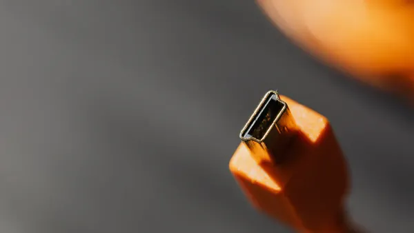
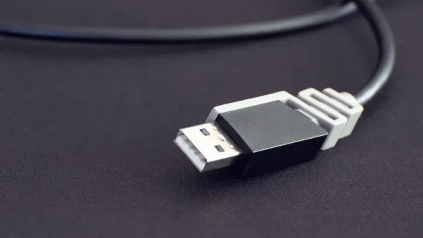
You can spot a type-a usb connector by its flat and rectangular shape. This design makes it easy to recognize among other usb connectors. The type-a usb connector has a solid, sturdy build. It uses a single row of contacts inside the plug. These contacts line up with the pins in the port. The connector only fits one way, so you avoid plugging it in upside down. Unlike newer connectors like USB-C, the usb type a does not support reversibility. You must check the orientation before you insert it.
The type-a connector first appeared in 1996. Early versions supported speeds up to 1.5 Mbps. Over time, the usb type a evolved. Newer versions added more pins for faster data transfer and extra features. Most type-a usb connectors still use four main pins, but USB 3.0 and above have up to nine pins. This change helps you get better performance from your devices.
- The type-a usb connector is flat and rectangular.
- It uses four pins for power and data in older versions.
- The design prevents reverse fitting, so you always insert it the right way.
Identifying USB Type A
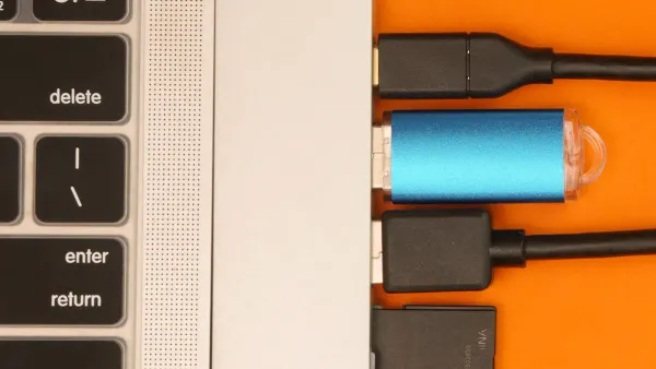
You find usb type a connectors on many devices. Look for a rectangular, flat plug or port. Most computers, laptops, and chargers use usb type a ports. You can also see them on game consoles, tablets, and media players. Keyboards, mice, flash drives, and external hard drives often use this connector. Printers and scanners also rely on the type-a connector for data transfer.
Color coding helps you tell the usb version. White ports mean USB 1.x. Black ports show USB 2.0. Blue ports mark USB 3.0. Teal ports stand for USB 3.1 Gen 1. Red ports mean USB 3.1 Gen 2 or USB 3.2. Some yellow or orange ports offer higher power or charging even when the device is off.
Tip: Always check the color inside the usb type a port. This quick step helps you pick the right cable for your device and get the best speed.
You use usb type a connectors to link peripherals to host devices. For example, you connect a keyboard or mouse to a computer using a type-a usb connector. You also use usb type a ports to charge smartphones or transfer files from a flash drive. The type-a connector remains one of the most common ways to connect and power your devices.
USB Pinout Compatibility
USB 2.0 vs USB 3.0
When you look at the usb type a connectors, you notice some important differences between USB 2.0 and USB 3.0. The main difference is the number of pins inside the connector. USB 2.0 uses four pins. These pins handle power, ground, and the usb data lines for data transfer. You see these four pins in almost every older type-a connector.
USB 3.0 takes things further. It adds five more pins, making a total of nine pins. These extra pins allow for much faster data transfer and better performance. The new pins sit deeper inside the connector, so you still see the same shape on the outside. The extra pins do not change the way you plug in the connector. You can use a USB 3.0 plug in a USB 2.0 port, but you only get USB 2.0 speeds.
Here is a table to help you compare the pinout for USB 2.0 and USB 3.0:
| Feature | USB 2.0 Type A | USB 3.0 Type A |
|---|---|---|
| Number of Pins | 4 | 9 |
| Pinout Diagram | Standard 4-pin | 4 main + 5 extra |
| Max Data Rate | 480 Mbps | 5 Gbps |
| Wire Colors | Red, White, Green, Black | Adds Blue/Other for extra pins |
You can spot a USB 3.0 type-a connector by the blue color inside the port or plug. This color helps you pick the right cable for your device. If you want the fastest data transfer, always use a USB 3.0 cable with a blue port.
Note: The extra pins in USB 3.0 do not affect the main four pins. You still use the same usb pinout for basic power and data.
Backward Compatibility
You do not need to worry about using older devices with newer ports. USB type a connectors support backward compatibility. This means you can plug a USB 2.0 device into a USB 3.0 port, and it will still work. The usb pinout stays the same for the main four pins, so your device connects safely.
Backward compatibility works because USB 3.0 uses a dual-bus design. This design lets the connector talk to both USB 2.0 and USB 3.0 devices. When you connect a USB 2.0 device to a USB 3.0 port, the connection uses USB 2.0 speeds. You do not get the faster data transfer, but your device still works.
- USB 3.0 uses a dual-bus system, so it can talk to both USB 2.0 and USB 3.0 devices.
- You can connect older devices to newer ports without problems.
- The speed drops to USB 2.0 levels if you use an older device.
You should always check the pinout diagram before wiring or repairing cables. The usb a pinout for USB 2.0 and USB 3.0 looks similar, but the extra pins in USB 3.0 give you more features. If you use the wrong cable or port, you might not get the speed you want.
Be careful when you use A-to-A cables. Type a usb pinout shows that both ends supply power. If you connect two devices with standard A-to-A cables, you risk electrical problems. Some special A-to-A cables have built-in electronics to keep things safe, but most do not.
- Standard A-to-A cables can cause electrical issues because both ports supply power.
- Only use A-to-A cables with built-in safety features.
- Always check your cable type before connecting two devices.
Tip: Always match your cable and port to the device you use. Look for the blue color in USB 3.0 type-a ports for the best speed. Use the correct usb pinout to avoid mistakes.
When you understand usb pinout compatibility, you make better choices for your projects. You keep your devices safe and get the best performance. The type a usb pinout helps you connect, repair, and upgrade your tech with confidence.
Wiring and Safety Tips
Soldering Practices
When you work with usb type a connectors, good soldering practices help you get a strong and reliable connection. You want each pin to connect cleanly to the board. Follow these steps for the best results:
- Use a fine tip on your soldering iron for better control.
- Apply flux to the connector pins and all the pads on the board.
- Pre-tin each connector pin before you start.
- Align the connector on the board, leaving a little extra space on each pad.
- Hold the connector steady and solder one side flap first.
- Solder the other side flap, making sure the connector does not move.
- Solder each pin to its pad by touching the tip to the extra space and adding solder carefully. Avoid making solder bridges between pins.
You can use these steps to keep your usb type a pinout clean and safe. A good solder job helps your usb devices work without problems.
Common Mistakes
Many people make simple mistakes when wiring usb type a connectors. You can avoid most problems if you know what to look for:
- Incorrect orientation: Always check the usb symbol before you insert the connector. It only fits one way.
- Wrong usb type: Make sure the connector matches the port. Using the wrong type can damage your device.
- Dust and debris: Clean usb type a ports often. Dust can block the connection.
- Physical damage: Look for bent pins or broken connectors before you use them.
- Outdated drivers: Update your usb drivers so your computer recognizes the device.
Tip: Double-check the pinout and pin configuration before you solder or connect any usb type a cable.
Safety Precautions
You need to stay safe when working with usb type a wiring. Incorrect wiring can cause electrical hazards. Here are some risks you should watch for:
- Short circuits can happen if you connect the wrong pins. This can damage both your device and the usb port.
- Overvoltage may occur, especially with newer usb standards that allow higher voltages.
- The close spacing of pins in usb type a connectors increases the risk of accidental shorts.
Always check your usb pinout before you connect power. Use the correct pin configuration for your project. If you see sparks or smell burning, unplug the device right away.
Remember: Careful wiring and regular checks keep your usb type a connectors safe and reliable.
Troubleshooting USB Type A
Diagnosing Issues
You may face several problems when using usb type a connectors. Common issues include errors in data transfer, power problems, and device recognition failures. Here are some frequent problems you might see:
- Improper USB packet data or data sequencing can cause dropped connections and slow data transfer.
- Power or VBUS issues may lead to devices shutting down if they draw too much current.
- Enumeration problems can stop your computer from recognizing the device.
To diagnose these issues, start by checking the physical condition of your usb cable and port. Look for bent pins or broken connectors. Use a multimeter to measure voltage between the ground and power pins. A cable tester can help you find open circuits or shorts. If you still have trouble, try your device on another computer or port.
| Diagnostic Tool | Purpose |
|---|---|
| Multimeter | Measure voltage between pins |
| Cable Tester | Check for opens, shorts, and resistance |
| USB Multimeter | Test data transfer and protocol support |
Tip: Always check your usb pinout and pinout diagram before testing. This step helps you avoid mistakes and keeps your devices safe.
Pinout Problems
Pinout problems often cause usb type a devices to fail. You might see issues if the pins do not line up with the pinout diagram or if the wiring does not match the usb a pinout standard. Follow these steps to find pinout problems:
- Inspect the cable for damage or bent pins.
- Use a multimeter to check voltage between ground and power.
- Test the cable with a cable tester for shorts or open lines.
- Update your device drivers.
- Try the device on another port or computer.
- Replace damaged cables or ports if needed.
If you use the wrong pinout, your device may not work or could get damaged. Always compare your wiring to the usb pinout and usb a pinout diagrams before connecting anything.
Quick Fixes
You can solve many usb type a problems with a few simple steps:
- Check all cable connections and make sure they are secure.
- Try different usb ports on your computer.
- Restart your computer to clear temporary glitches.
- Open Device Manager and look for driver errors. Update or reinstall drivers if needed.
- Update your operating system and drivers.
- Adjust power management settings to keep usb ports active.
- Make sure your devices do not overload the usb port’s power limit.
- Check BIOS or UEFI settings to confirm usb support is enabled.
- Test your device and cable on another computer.
| USB Tester Name | Key Features | Price Range |
|---|---|---|
| PowerJive USB meter | High accuracy, measures voltage, current, and capacity | Moderate |
| KWS-V30 USB tester | Overcurrent protection, multiple displays | Affordable |
| Klien Tools ET920 | Tests both Type-C and Type-A cables, high quality | Slightly High |
Note: Regularly checking your usb type a connectors and using the correct usb pinout will help you avoid most problems. Reliable connections depend on careful inspection and proper use of the pinout diagram.
USB A Pinout Reference
Pin Table
You need a clear pin table when you work with usb type a connectors. This table helps you wire, repair, or check any usb cable. Each pin has a color and a job. You can use this table to avoid mistakes and make sure your usb pinout matches the standard.
| Pin | Name | Cable Color | Description |
|---|---|---|---|
| 1 | VCC | Red | +5 VDC power supply pin |
| 2 | D- | White | Data- pin |
| 3 | D+ | Green | USB data cable Data+ |
| 4 | GND | Black | Ground pin |
You see these four pins in every usb type a connector. The red wire gives power. The white and green wires send and receive data. The black wire connects to ground. If you use usb 3.0, you find extra pins for faster speeds, but the main four pins stay the same. Always check your usb pinout before you start a project.
Tip: Match the wire colors to the pinout table. This step helps you avoid wiring errors and keeps your devices safe.
Quick Summary
You can use this quick summary to remember the key facts about usb type a connectors. This table shows you what makes usb type a special and how it works in your projects.
| Feature | Description |
|---|---|
| Connector Type | Type-A USB is the most widespread type of USB connector. |
| Connection Direction | Type-A USBs only allow downstream connections, connecting to hosts. |
| Connector Shape | Flat and rectangular shape. |
| Versions | Two versions: male (plug) and female (socket/port). |
| Common Uses | Found on host controllers, computers, flash drives, keyboards, and mice. |
| Reversibility | Type A USBs aren’t reversible, which can lead to incorrect insertion. |
| Color Coding | USB 2.0 connectors are white, while USB 3.0 connectors are blue. |
| Connection Success Rate | Proper alignment of pin housings ensures a successful connection almost 100% of the time. |
You find usb type a connectors on many devices. You use them for data transfer, charging, and connecting peripherals. The usb pinout helps you make reliable connections every time. You can trust the pinout diagram to guide your wiring and repairs.
Note: Keep this usb pinout reference handy for your DIY electronics projects. You save time and avoid mistakes when you check the pinout before you connect anything.
When you master the type a usb pinout, you make your usb type a projects safer and more reliable. You use the usb pinout table below to wire each usb type a connector correctly and avoid mistakes:
| Pin Number | Color | Function |
|---|---|---|
| 1 | Red | +5V (power supply) |
| 2 | White | Data- (send data) |
| 3 | Green | Data+ (receive data) |
| 4 | Black | Ground (complete circuit) |
You keep your usb devices working well when you check the pinout before every project. For more help, explore these resources:
- The article ‘What Are USB Pinouts and Why Are They Crucial for Your Devices?’ explains usb pinout basics and troubleshooting.
- ‘USB Pinout: Everything You Need to Know’ covers usb type a wiring in detail.
- ‘USB A Pinout: A Comprehensive Guide to Understanding and Using the Configuration’ focuses on usb type a pinout.
Always use safe wiring and check the connector type. You improve data transfer and power delivery when you understand the usb type a pinout.
FAQ
What is the main difference between USB Type A and USB Type C?
You can spot the difference by shape. USB Type A has a flat, rectangular design. USB Type C is smaller and oval. USB Type C supports reversible insertion and faster data speeds.
Can you use a USB 3.0 device in a USB 2.0 port?
Yes, you can use a USB 3.0 device in a USB 2.0 port. The device will work, but you only get USB 2.0 speeds. The connection stays safe and reliable.
How do you identify the correct USB pinout for wiring?
You should check the color of each wire and match it to a pinout table. Red is power, black is ground, green and white are data. Always use a trusted USB pinout diagram.
Why does my USB device not get recognized by my computer?
Your USB device may not work if the cable is damaged, the port is dirty, or the drivers are outdated. Try another port, clean the connector, or update your drivers.
Tip: Always check your USB cable and port for physical damage before troubleshooting software issues.