How to Decode Capacitor Markings
You pick up a small capacitor and see numbers, letters, or even colored bands. What do these capacitor markings mean? You ne

You pick up a small capacitor and see numbers, letters, or even colored bands. What do these capacitor markings mean? You need to know the value, tolerance, and polarity to use it safely in your circuit. Different systems exist for marking capacitors, including direct printing, three-digit codes, letter codes, and color codes.
| Marking System | Description |
|---|---|
| Direct Marking | Directly prints the value and unit on the capacitor, e.g., '100µF' or '10nF'. |
| Three-Digit Code | Uses two significant figures and a multiplier, e.g., '104' means 100 nF. |
| Letter Code | Uses letters to indicate values, e.g., '4u7' for 4.7µF. |
| Color Codes | Older method using color bands to indicate values, now largely phased out for modern components. |
With the right approach, decoding these markings becomes simple.
Key Takeaways
- Learn to identify capacitor markings by looking for numbers, letters, or color bands. This helps you understand the value, voltage rating, and polarity.
- Always check for polarity markings on polarized capacitors. Incorrect connections can damage your circuit or cause safety hazards.
- Use a multimeter to test capacitors before installation. This ensures they are functioning correctly and match the required specifications.
- Organize your capacitors by value and voltage. This practice simplifies your work and reduces the risk of mistakes.
- Keep a reference chart handy for decoding markings. This tool helps you quickly identify values and avoid errors in your projects.
Quick Start: Capacitor Markings
How to Read a Capacitor
When you pick up a capacitor, you often see markings that look confusing at first. You can learn to read a capacitor quickly by following a few simple steps. First, look for numbers, letters, or colored bands on the body. These markings tell you the value, voltage rating, and sometimes the tolerance. If you see a stripe or a plus sign, check for polarity. Many electrolytic and tantalum capacitors are polarized, so you must connect them the right way. If you connect them backward, you risk damaging your circuit.
Here is a quick guide to help you decode capacitor markings:
- Find the value marking. It might be a printed number, a digit code, or a color band.
- Check for a voltage rating. This is usually printed near the value.
- Look for polarity markings. A stripe or a longer lead often shows the negative or positive side.
- Use a capacitor code chart or a general capacitor codebreaker to match codes to values.
- Double-check with a capacitor reference chart if you feel unsure.
Tip: Always test a capacitor with a meter before using it. Label your components and keep them organized by value and voltage.
Common Marking Formats
You will see different marking formats on different kinds of capacitors. Each format helps you identify the right component for your project. Here is a table that shows the main types of capacitor markings:
| Type of Code | Description | Common Usage |
|---|---|---|
| Color Codes | Colored bands show values, mostly on small capacitors. | Small capacitors (e.g., mica) |
| Digit Codes | Digits and letters represent values, often on ceramic disk capacitors. | Ceramic disk capacitors |
| Printed Value Markings | Values printed directly, used for larger capacitors. | Larger capacitors |
You should always check for tolerance and polarity when reading capacitor markings. Some capacitors have a stripe to show the negative side. Others use a longer lead for the positive side. If you ignore these markings, you might connect the capacitor incorrectly. That can cause the capacitor to fail or even damage your circuit.
Common mistakes include missing the polarity marking, using a capacitor with too low a voltage rating, or mixing up values. You can avoid these problems by using a capacitor reference chart and testing each capacitor before use. When you organize your capacitors by value and voltage, you make your work easier and safer.
Types of Capacitors
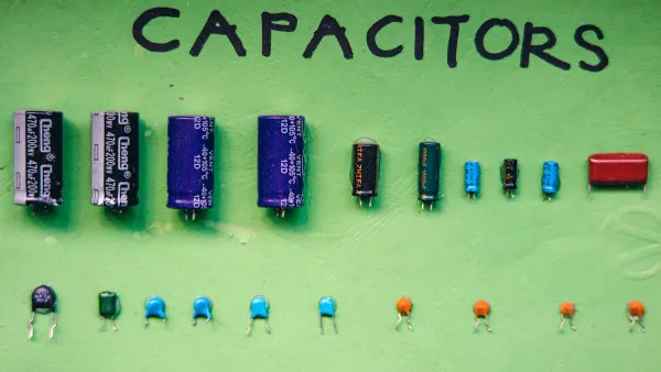
Capacitors come in several types, and each type uses different markings to show important information. You need to know how to read these markings to choose the right part for your circuit. Here is a table that compares the main types of capacitors and their marking conventions:
| Type of Capacitor | Characteristics | Marking Conventions |
|---|---|---|
| Ceramic | Non-polar, low ESR, sensitive to temperature and voltage | Three-character alphanumeric coding system based on class |
| Electrolytic | High capacitance, polarized, stable at high voltage | Typically marked with capacitance value and voltage rating |
| Plastic Film | Larger size, useful in high-frequency circuits | Marked with capacitance value and tolerance specifications |
Electrolytic Capacitor Markings
You often use an electrolytic capacitor when you need high capacitance. These capacitors are polarized, so you must pay close attention to their markings. Most of the time, you will see the capacitance value and voltage rating printed right on the body. For example, you might see "100μF 25V." Manufacturers use a '-' sign to show the negative lead. Sometimes, you will see a voltage code, like a single letter or two digits, to show the voltage rating. Always check for the polarity marking before you install the part.
Tip: If you connect an electrolytic capacitor backward, it can fail or even explode.
Tantalum Capacitor Markings
Tantalum capacitors also have special markings. You will see a '+' sign to show the positive terminal. The capacitance value is printed directly on the body, so you can read it easily. These capacitors are polarized, and incorrect polarity can cause damage. Other types may use codes or color bands, but tantalum capacitors make polarity clear with the '+' sign. Always double-check the markings before you place the part in your circuit.
Ceramic & Film Capacitor Markings
Ceramic and film capacitors use different marking formats. You will often see a three-digit code, like "104," which means 100,000 pF or 0.1 μF. Some film capacitors show the value, tolerance, and voltage, such as "105K 330V." Here is a table with common marking formats you might find:
| Marking Format | Description |
|---|---|
| Manufacturer's name or trademark | Shows who made the capacitor |
| Rated capacitance | Tells you the value, like 473M for 47 nF |
| Tolerance | Shows how much the value can change, like ±10% |
| Rated voltage | Maximum voltage, such as 100V or 330V |
| Certification marks | Shows safety standards |
You should always read the markings carefully. This helps you avoid mistakes and keeps your circuits safe.
Decoding Capacitor Markings
Understanding capacitor markings helps you select the right part for your electronic project. You can break down the process into three main areas: value codes and units, tolerance codes, and color codes. Each area gives you important information about the capacitor’s function and reliability.
Value Codes and Units
You often see numbers or codes on capacitors. These markings tell you the value of the capacitor, which is its ability to store electrical charge. To decode these markings, follow these steps:
- Identify the capacitor type. Check if you have a ceramic, electrolytic, tantalum, or another type. This step helps you know which coding system to use.
- Look for markings. Find numbers, letters, or color bands. Some surface-mount capacitors may not have visible markings, so you might need to check the manufacturer’s documentation.
- Decode the value. Use the numeric code. For example, "104" means 100,000 picofarads (pF) or 0.1 microfarads (μF). Sometimes, you see an EIA code like "A5," which also means 0.1 μF.
- Check for voltage and tolerance. Look for extra numbers or letters that show the voltage rating and tolerance.
- Verify polarity if needed. For polarized capacitors, make sure you know which side is positive or negative.
Capacitor values use the farad (F) as the standard unit. Most capacitors in electronics use much smaller units:
- Microfarads (μF): 1 F = 1,000,000 μF
- Nanofarads (nF): 1 F = 1,000,000,000 nF
- Picofarads (pF): 1 F = 1,000,000,000,000 pF
You will often see these units in the markings. For example, a marking of "10μF" means the value is ten microfarads. The international standards for these codes help keep things clear. Here is a table showing the main standards:
| Standard | Year | Description |
|---|---|---|
| IEC 60062 | 1952 | Notation for resistor and capacitor values |
| DIN 40825 | 1973 | Accepted the RKM code |
| BS 1852 | 1975 | Accepted the RKM code |
| IS 8186 | 1976 | Accepted the RKM code |
| EN 60062 | 1993 | Accepted the RKM code |
| IEC 60062:2016 | 2016 | Most recent release of the standard |
You should always match the value on the capacitor to the value needed in your circuit. Using the wrong value can cause your circuit to work poorly or not at all.
Tolerance Codes
Capacitor tolerance tells you how much the actual value can differ from the stated value. You find this information in the markings, often as a letter code. For example, a "K" in "104K" means the tolerance is ±10%. This means the real value can be 10% higher or lower than what is marked.
You might see other letters for different tolerances:
- "J" means ±5%
- "K" means ±10%
- "M" means ±20%
Manufacturers use these codes to help you pick the right part for your needs. If your circuit needs a precise value, choose a capacitor with a tight tolerance. If the value can vary more, a wider tolerance is fine. Always check the markings for the tolerance code before you use the capacitor.
Color Codes
You may find color codes on older capacitors. These markings use colored bands to show the value, tolerance, and sometimes the voltage rating. The use of color codes started in the late 1930s when small capacitors became common. This method lasted until the mid-1970s, when printing numbers and letters became cheaper and easier.
Today, you might still see color codes on some vintage or specialty capacitors. Each color stands for a number. You read the bands in order to find the value. Some systems also use colors for tolerance and voltage. This can be confusing because different systems exist.
- Color codes can show capacitance, tolerance, and voltage.
- You should use a color code chart to decode these markings.
- Most modern capacitors use printed numbers instead of color codes.
Note: If you find a capacitor with color bands, double-check the value with a chart. This helps you avoid mistakes in your circuit.
You now know how to decode the value, tolerance, and color code markings on capacitors. This skill helps you choose the right component and build safe, reliable circuits.
Identify Capacitor Polarity
Understanding how to identify capacitor polarity is essential for anyone working with electronic components. If you install a polarized capacitor incorrectly, you risk damaging your circuit or causing safety hazards. You can determine capacitor polarity by learning to spot the right visual clues and following best practices.
Polarity Markings
You will find several reliable ways to determine capacitor polarity on different types of capacitors. Manufacturers use clear markings to help you identify capacitor polarity before installation. Here are the most common visual indicators:
| Indicator Type | Description |
|---|---|
| ‘+’ and ‘-’ signs | Markings near the terminals indicating positive and negative. |
| Colored bands | Darker band marks the negative terminal. |
| Lead lengths | Positive lead is longer than the negative lead. |
| Circuit board markings | Symbols on the board indicate terminal positions. |
You can also look for these features:
- A stripe or band on the negative side
- A '+' symbol near the positive lead
- A '-' symbol near the negative lead
- Longer lead for the positive terminal (in through-hole capacitors)
- Black or dark-colored end cap for the negative terminal
- Silver or light-colored end cap for the positive terminal
Electrolytic capacitors usually have a stripe on the body to show the negative terminal. Tantalum capacitors often use a '+' sign to mark the positive terminal. Always check both the capacitor and the circuit board for these markings. If you see a longer lead, it usually means the positive side, but do not rely only on lead length. Leads can be trimmed during assembly or repair.
Tip: Always double-check the markings on both the capacitor and the PCB before you install the part. If you feel unsure, consult the datasheet or use a multimeter to help determine capacitor polarity.
Correct Capacitor Polarity
You must always use the correct capacitor polarity when installing polarized capacitors. If you connect a polarized capacitor backward, you can cause serious problems. Here are some possible consequences:
| Consequence | Description |
|---|---|
| Destruction of Capacitor | Incorrect polarity can destroy the dielectric and the capacitor itself. |
| Fire | The failure of the capacitor can lead to fire hazards. |
| Explosion | An incorrectly installed capacitor may explode, posing safety risks. |
When you determine capacitor polarity, remember that electrolytic and tantalum capacitors have different marking styles. Electrolytic capacitors use a stripe for the negative side, while tantalum capacitors use a '+' for the positive side. Mixing up these rules is a common mistake. Do not judge only by lead length, since leads may be cut short. Supercapacitors also need correct capacitor polarity, even though they can handle high currents. Outer foil bands on film capacitors do not show polarity; they only help with shielding.
To avoid mistakes, follow these best practices:
- Double-check the polarity markings on both the capacitor and the PCB.
- Use a multimeter to check for lower resistance on the negative lead of electrolytic capacitors.
- Consult the datasheet if you are not sure about the orientation.
- Use automated testing equipment in production to confirm correct capacitor polarity.
- Refer to circuit diagrams for extra guidance.
Note: Non-polarized capacitors do not have these risks, but always check the type before installation.
You can identify capacitor polarity by looking for clear signs like stripes, bars, or lead length. Always determine capacitor polarity before soldering. Using the correct capacitor polarity keeps your circuit safe and prevents dangerous failures. Practice these steps every time you work with polarized capacitors to build reliable electronic projects.
Verify and Troubleshoot
Use a Multimeter to Read a Capacitor
You can use a multimeter for testing capacitors and confirming their values. This step is important, especially when you cannot trust the markings or need to check if a capacitor is still good. Many people use this method for electrolytic and polarized capacitors, as well as for other types.
Follow these steps for accurate testing:
- Disconnect the capacitor from the circuit. This prevents errors during testing.
- Discharge the capacitor safely. Use a resistor and wait five seconds to avoid shocks.
- Check the value printed on the capacitor. This helps you know what to expect.
- Set your multimeter to the capacitance mode.
- Attach the multimeter leads to the capacitor terminals.
- Wait for the reading to stabilize. Compare the result with the marked value.
Tip: Always make sure the capacitor is fully discharged before testing. This keeps you safe and protects your meter.
You should also consult your multimeter’s manual for special instructions. Some meters have a Relative mode for low values. Testing is especially important for electrolytic and polarized capacitors, as their performance can change over time.
| Step | Limitation |
|---|---|
| Detach Capacitor | Necessary to avoid measurement errors |
| Display 'OL' | Indicates a faulty capacitor or exceeds measurement range |
If you see "OL" on your meter, the capacitor may be faulty or too large for your meter to measure. Testing helps you catch these problems before you install the part.
Troubleshooting Marking Issues
Sometimes, you face problems with visual identification of capacitor markings. Markings can wear off or become hard to read. Micro cracking and delamination often cause this damage, especially in MLCC capacitors. These issues can happen from board flexing or manual soldering. Over time, moisture can get inside and cause failure.
When you cannot read the markings, try these troubleshooting steps:
- Look for any remaining visual identification clues, such as stripes or lead length, especially on electrolytic and polarized capacitors.
- Remember that older capacitors sometimes used confusing terms like In and Out, or Plus and Minus. Modern polarized capacitors use clear symbols, but always double-check.
- For AC circuit capacitors, know that some are non-polarized and can be installed either way.
- If you cannot identify the value or polarity, use your multimeter for testing. This works well for electrolytic and polarized capacitors.
- If all markings are gone, compare the capacitor to a known good one or consult the circuit diagram.
Note: Always handle capacitors gently during testing and installation. This reduces the risk of damaging the markings or the component itself.
Testing and careful visual identification help you avoid mistakes with electrolytic and polarized capacitors. You can keep your circuits safe and reliable by following these steps.
Decoding capacitor markings becomes easy when you follow these steps:
- Read the three-digit code for capacitance.
- Check the tolerance letter and voltage rating.
- Confirm polarity before installation.
Always use a multimeter to verify values and double-check orientation. Mistakes can cause power instability, poor filtering, or even damage your circuit.
Keep a reference chart handy, like the SparkFun Capacitor Kit Guide or a conversion table.
Practice with real components. You will build confidence and create safer, more reliable electronic projects.
FAQ
How do you know if a capacitor is polarized?
You can spot a polarized capacitor by looking for a stripe, a plus or minus sign, or a longer lead. Electrolytic and tantalum capacitors are usually polarized. Always check these markings before you place the part in your circuit.
What does the three-digit code on a ceramic capacitor mean?
The three-digit code shows the capacitance value in picofarads (pF). The first two digits are the value, and the third digit is the multiplier. For example, "104" means 100,000 pF or 0.1 μF.
Can you use a capacitor with a higher voltage rating?
Yes, you can use a capacitor with a higher voltage rating than required. It will work safely in your circuit. Never use a capacitor with a lower voltage rating than your circuit needs.
What should you do if the capacitor markings are unreadable?
Use a multimeter to measure the capacitance. If you cannot test it, compare it to a known good capacitor or check the circuit diagram. Always replace damaged or unmarked capacitors to keep your circuit safe.
Why is capacitor tolerance important in circuits?
Capacitor tolerance tells you how much the actual value can change from the marked value. In timing or filter circuits, tight tolerance helps your circuit work as designed. Loose tolerance can cause errors or unstable performance.