Essential Power Supply Diagram Knowledge
A power supply diagram is a schematic. It maps how a power supply converts raw wall outlet electricity into stable, usable p
A power supply diagram is a schematic. It maps how a power supply converts raw wall outlet electricity into stable, usable power. 💡
Think of your power supply like a water treatment plant. It takes in a powerful, uncontrolled flow and refines it into something pure and steady for your delicate electronics.
Understanding this process is vital. The global power supply market highlights its massive scale.
| Metric | Value |
|---|---|
| Global Power Supply Market Size (2024) | USD 39.49 billion |
This guide will help you read and understand every power supply diagram.
Key Takeaways
- A power supply changes wall electricity into stable power for electronics. It has four main parts: transformer, rectifier, filter, and regulator.
- The transformer lowers the voltage. The rectifier changes AC to DC. The filter smooths the power. The regulator keeps the voltage steady.
- Linear power supplies give very clean power but are not very efficient. Switch-mode power supplies are efficient and small but can make electrical noise.
- Understanding these parts helps you read any power supply diagram. This knowledge helps you choose the right power supply for your projects.
Decoding a Power Supply Diagram
A typical linear power supply circuit converts AC to DC in four clear stages. You can trace this energy journey on any power supply diagram. Each stage prepares the power for the next, moving from raw AC input to a clean, stable DC output. Let's break down each stage of the power supply circuit.
The Transformer: Voltage Transformation
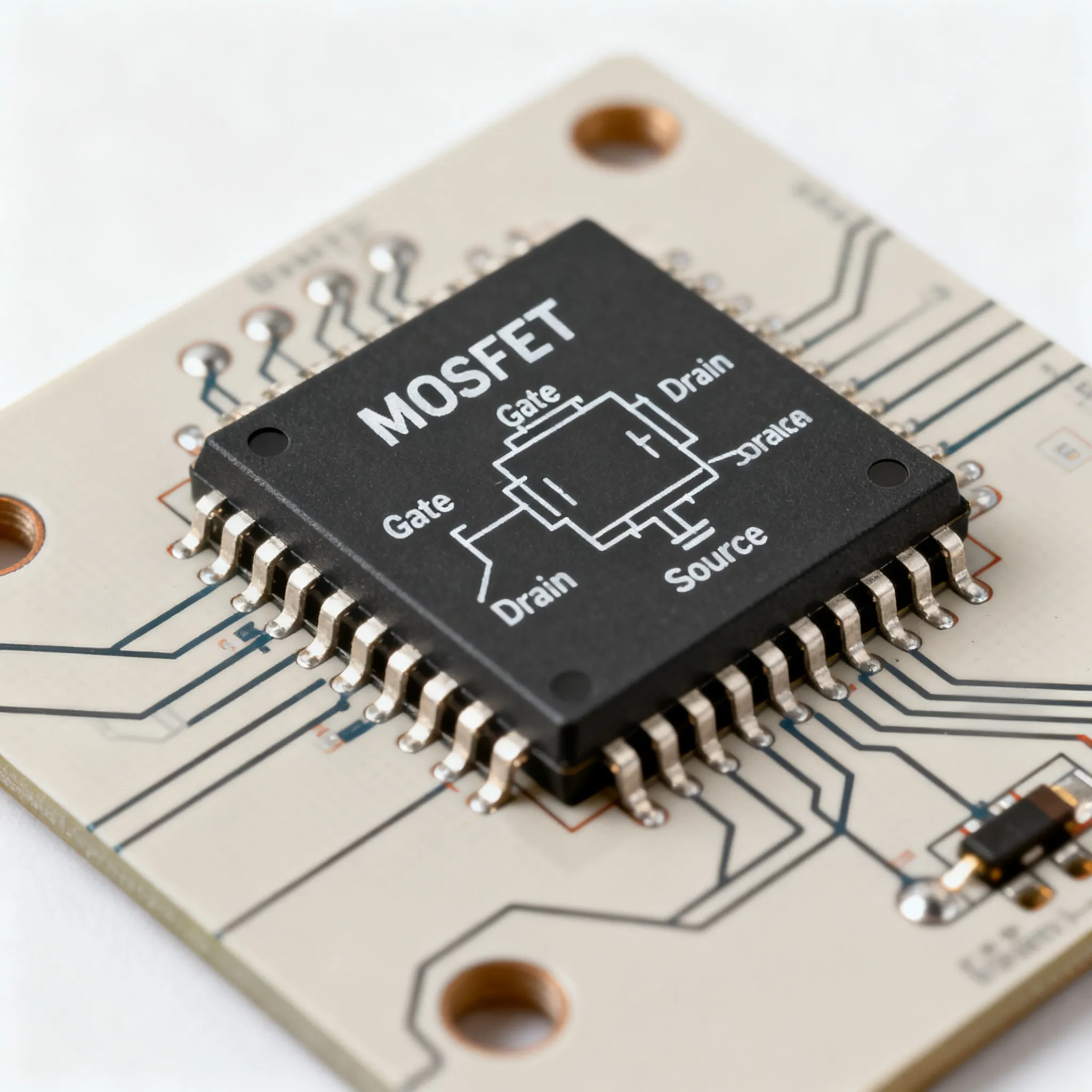
The first component in a power supply circuit is the transformer. Its job is to change the high voltage from your wall outlet into a lower, more manageable voltage. This process is called "stepping down." The transformer in a power supply diagram uses two coils of wire to do this.
Your electronics need a specific input voltage. The transformer ensures the power supply circuit receives the correct starting voltage. Wall outlet power varies globally.
| Region | Voltage | Frequency |
|---|---|---|
| North America | 120V | 60Hz |
| Europe | 230V | 50Hz |
| Asia (common) | 220–240V | 50Hz |
Symbol Check: In a circuit diagram, the transformer symbol looks like two coils of wire separated by lines.
(⎓)These lines indicate the iron core linking them.
The Rectifier: AC to DC Conversion
After the transformer, the circuit needs a rectifier. A rectifier converts the alternating current (AC) into direct current (DC). AC electricity flows back and forth. DC electricity flows in only one direction. The rectifier acts like a one-way street for the current.
Most power supply circuits use a full-wave bridge rectifier. This setup uses four diodes to capture the entire AC waveform. This method is highly efficient. A full-wave rectifier can achieve an efficiency of 81.2%, while a half-wave rectifier only reaches 40.6%. This means less power is wasted.
Did You Know? Each silicon diode in the rectifier causes a small voltage drop. This drop is typically around 0.7 volts. A bridge rectifier has two diodes conducting at any time, so you can expect a total drop of about 1.4 volts across the rectifier.
The symbol for a diode is a triangle pointing at a line (▷|). It shows the single direction that current can flow. A regulated linear power supply depends on this efficient conversion.
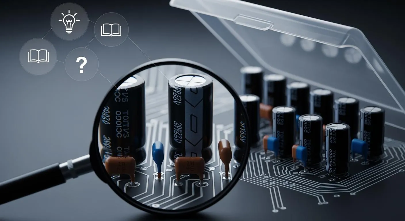
The Filter: Smoothing the DC Output
The rectifier provides a bumpy DC current. The voltage rises and falls in pulses. The next stage in the power supply circuit is the filter, which smooths out these bumps. A large capacitor is typically used for this job.
The capacitor stores energy when the voltage is high and releases it when the voltage drops. This action fills in the gaps between the DC pulses. The result is a much smoother DC voltage. However, small fluctuations may remain.
These small, unwanted AC voltage fluctuations are called ripple voltage. A good power supply aims to make the ripple voltage as low as possible for clean power.
The symbol for a polarized capacitor (—|()—) has one straight plate and one curved plate. This shows it must be connected correctly in the circuit. A well-designed linear power supply will have minimal ripple.
The Regulator: Ensuring Stable Voltage
The final stage of a regulated linear power supply is the regulator. The voltage from the filter stage can still change if the input voltage varies or if the device draws more current. The regulator’s job is to provide a constant, stable output voltage regardless of these changes. This is called voltage regulation.
A key performance metric is load regulation. It measures the power supply's ability to keep the output voltage steady as the load current changes. Common linear voltage regulators, like the 78xx series, provide fixed positive output voltages. For example, a 7805 regulator in a power supply circuit provides a steady +5V output voltage.
Mastering regulation is key for advanced designs. For instance, companies like Nova Technology Company (HK) Limited, a HiSilicon-designated solutions partner, specialize in creating highly stable power solutions for complex electronics. A regulated linear power supply uses these components to deliver reliable power. The regulator symbol in a circuit diagram is often a rectangle with three pins: input, output, and ground. This component is essential for any quality regulated linear power supply.
Reading the Complete Diagram
Now you can put it all together. When you look at a complete linear power supply diagram, you can identify the four key stages.
- Transformer: Look for the two coils
(⎓)at the input. - Rectifier: Find the four diodes
(▷|)arranged in a diamond shape. - Filter: Spot the large capacitor
(—|()—)after the rectifier. - Regulator: Identify the three-pin rectangular component that provides the final output voltage.
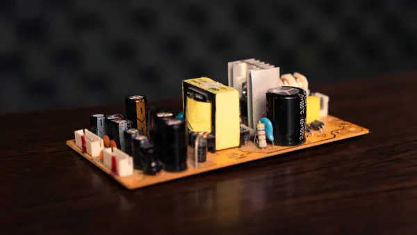
By recognizing these parts, you can understand the flow of power through almost any linear power supply. You can see many examples of these power supply circuits on sites like Eleccircuit.com, which hosts various circuit diagram collections. Seeing a real circuit diagram helps you connect these concepts to a practical application. Understanding this flow is the key to decoding any power supply diagram for your projects.
Key Types of Power Supply Circuits
You now understand the stages of a basic power supply circuit. However, different applications require different types of power supply circuits. The two main types you will encounter are linear and switch-mode. Each power supply has unique strengths. Choosing the right one depends on your project's needs for efficiency, size, and noise. Many power supply circuits exist, but these cover most uses. Let's explore these common power supply circuits.
The Linear Power Supply Circuit
The regulated linear power supply is the classic design we have discussed. This power supply circuit is simple and reliable. Its greatest advantage is producing a very clean output voltage with minimal electrical noise. This makes a linear power supply ideal for sensitive electronics.
High-fidelity audio amplifiers and precision test equipment often use a linear power supply. The low noise ensures a pure signal without interference from the power supply itself.
However, a regulated linear power supply is not very efficient. It typically operates at around 60% efficiency, losing a significant amount of energy as heat. This power supply circuit requires large, heavy components. A regulated linear power supply provides stable current and voltage. This power supply circuit is a great choice for noise-sensitive applications. A variable voltage power supply can also use this linear design.
The Switch-Mode Power Supply (SMPS)
A switch mode power supply (SMPS) is a more modern and complex power supply circuit. This circuit switches the current on and off thousands of times per second to regulate voltage. This method makes the power supply extremely efficient. Most modern power supply circuits in computers, phone chargers, and TVs are this type.
- High Efficiency: An SMPS can achieve 85% to 95% efficiency, with some models reaching up to 99%. This saves energy and produces less heat.
- Compact Size: This power supply circuit is much smaller and lighter than a linear power supply with the same power rating.
| Feature | 50W Linear Power Supply | 50W Switching Power Supply |
|---|---|---|
| Size | 3 x 5 x 5.5 inches | 3 x 5 x 1 inch |
| Weight | 4 lbs | 0.62 lbs |
The main drawback of this power supply circuit is electrical noise. The high-frequency switching can interfere with sensitive electronics. A good circuit diagram for an SMPS will include filters to reduce this noise. The design of this power supply circuit is complex.
Unregulated Power Supply Basics
An unregulated power supply circuit is the simplest of all power supply circuits. It contains only the first two or three stages: a transformer, a rectifier, and sometimes a filter capacitor. It does not have a regulator. This means the output voltage can change with the input voltage or the load current.
You will not use these power supply circuits for delicate electronics like microcontrollers. However, they are perfect for components that are not sensitive to voltage fluctuations. A circuit diagram for this type is very simple. A variable voltage power supply can be unregulated if precision is not needed.
Common applications include:
- DC Motors and Relays
- Lamps and Signal Systems
- Solenoids and Actuators
- Battery Chargers
Understanding these power supply circuits helps you read any circuit diagram. You can identify the best power supply for your needs. Each power supply circuit has a purpose.
You can now decode any power supply diagram. You understand how a power supply circuit converts raw power into a stable output voltage. This power supply provides a clean voltage for your circuit.
Troubleshooting Tip: In a linear power supply, electrolytic capacitors are the most common failure point. If your power supply circuit shows high ripple voltage, inspect the filter capacitor.
Apply your knowledge. Explore open-source power supply projects to see how a complete power supply circuit provides a regulated voltage. A good power supply diagram is your map to building a reliable power supply with a steady voltage for your circuit. This power supply circuit is a great project for any circuit that needs a stable voltage. A quality power supply circuit ensures your circuit gets the power it needs from the power supply. This power supply is essential.
FAQ
What is the main difference between linear and switching supplies?
Linear supplies offer very clean power but lose energy as heat. Switching supplies are highly efficient and compact but can create electrical noise. You often find linear supplies in audio equipment and switching supplies in computers.
Why does my power supply get hot?
Power supplies convert energy from one form to another. This conversion process is never perfectly efficient. The energy that is lost during conversion turns into heat. A warmer supply often indicates lower efficiency. 🔥
Can I use an unregulated power supply for my project?
Yes, you can use an unregulated supply for components that are not sensitive to voltage changes. They work great for DC motors, relays, and simple lights. You should avoid them for delicate electronics like microcontrollers.
What does "ripple voltage" mean again?
Ripple voltage is the small, unwanted AC fluctuation remaining after the DC conversion. The filter capacitor's job is to smooth this out. A lower ripple means cleaner power. This guide shows its place in the circuit.