

A Practical Guide to the Capacitor Charge Formula
Have you ever seen this simple equation? Q = C * V This is the formula for charge on a capacitor. You can use it to unlock h
Have you ever seen this simple equation?
Q = C * V
This is the formula for charge on a capacitor. You can use it to unlock how a capacitor works. It connects the total charge (Q) to the capacitor's capacitance (C) and the voltage (V). Understanding this relationship is key to knowing how much charge stored in capacitor is possible. The capacitor is a vital part of modern electronics, with the global market showing significant growth.
| Metric | Value |
|---|---|
| Market Size (2024) | USD 25.49 billion |
| Projected Market Size (2032) | USD 40.66 billion |
| Compound Annual Growth Rate (CAGR) | 6.63% (2026-2032) |
This guide makes understanding capacitance and charge simple.
Key Takeaways
- The formula Q = C * V shows how much charge a capacitor stores. 'Q' is charge, 'C' is capacitance, and 'V' is voltage.
- Capacitance, or 'C', depends on the capacitor's physical build. This includes the size of its plates, the distance between them, and the material in between.
- Capacitors do not charge instantly. They charge over time. This charging speed depends on the capacitor's capacitance and the circuit's resistance.
- You must convert capacitance units to Farads for calculations. For example, change microfarads (µF) to Farads (F) before using the formula.
Understanding the Core Variables: Q, C, and V
The formula for charge on a capacitor, Q = C * V, is simple. You must first understand what each letter in the equation represents. Let's break down these core concepts for electronic components.
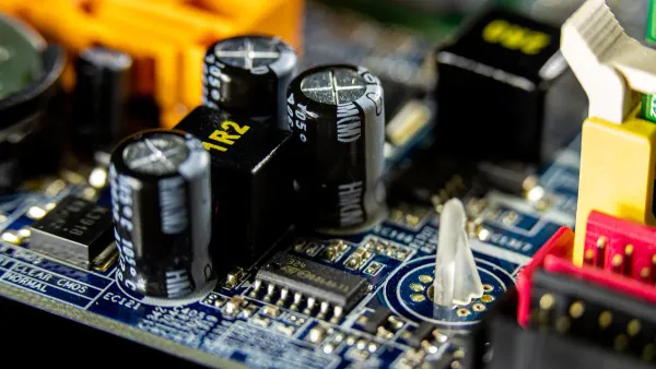
What is a Capacitor?
A capacitor is a component that stores electrical energy. Think of it like a tiny, rechargeable battery that charges and discharges very quickly. The first capacitor was the Leyden jar, invented independently by Ewald Georg von Kleist in 1745 and Pieter van Musschenbroek in 1746.
You can visualize how a capacitor works with a real-world analogy. A hydraulic accumulator stores fluid under pressure. Similarly, an electrical capacitor stores charge, providing a quick burst of energy when needed in a circuit.
Defining Charge (Q) in Coulombs
Charge (Q) measures the amount of electricity stored in the capacitor. The unit for electrical charge is the Coulomb (C). One Coulomb represents a huge number of electrons. It is equivalent to the charge of approximately 6.24 x 10^18 electrons. You will rarely work with a full Coulomb of charge in small electronic circuits.
Defining Capacitance (C) in Farads
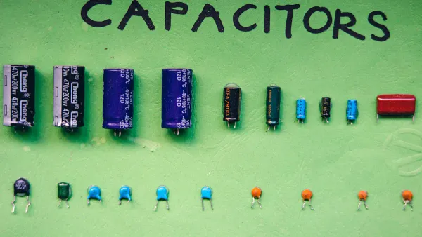
Capacitance (C) is the measure of a capacitor's ability to store charge. The unit for capacitance is the Farad (F). A one-Farad capacitor is extremely large for most electronics. You will typically see capacitance values in much smaller units:
- Microfarads (µF): One-millionth of a Farad.
- Nanofarads (nF): One-billionth of a Farad.
- Picofarads (pF): One-trillionth of a Farad.
The physical size of a capacitor does not always determine its capacitance.
Defining Voltage (V) in Volts
Voltage (V) is the electrical pressure or potential difference across the capacitor's two terminals. This pressure pushes the charge into the capacitor. You can get this voltage from a power source like a battery or a USB port. Different power sources provide different standard voltages.
| Battery Type | Standard Voltage |
|---|---|
| Disposable Alkaline AA | 1.5V |
| Rechargeable NiMH AA | 1.2V |
| Rechargeable Lithium-ion AA | 1.5V |
| Nickel-zinc AA | 1.6V |
Understanding the voltage of your power source is crucial for using any capacitor correctly.
Using the Formula for Charge on a Capacitor
You now understand the variables Q, C, and V. It is time to put them together. The formula for charge on a capacitor, Q = C * V, is your tool for calculating the total charge a capacitor holds when it is fully charged. This calculation is not just an academic exercise. It is critical for designing and troubleshooting many electronic circuits and integrated circuits.
Knowing the stored charge is essential in these applications:
- Flash Lamps: A capacitor stores a specific amount of charge. It then discharges it very quickly to power the bright flash in a camera.
- Surge Protectors: A capacitor in a circuit can absorb the charge from a sudden voltage spike. This protects sensitive electronic components from damage.
- Signal Processing: In DRAM (Dynamic Random-Access Memory), the charged or discharged state of a tiny capacitor represents a binary '1' or '0'. Calculating the charge helps engineers design reliable memory chips.
- Sensors: Some sensors measure things like air humidity or mechanical strain. They use a capacitor whose capacitance changes with the environment. The change in stored charge tells you the sensor's reading.
A Step-by-Step Calculation Guide
Using the formula for charge on a capacitor is straightforward. You can follow these three simple steps to get an accurate result every time.
- Identify Your Known Values. Find the capacitance (C) of your capacitor and the voltage (V) applied across it. The capacitance is usually printed on the side of the capacitor. The voltage comes from your power source, like a battery or power supply.
- Check and Convert Your Units. The equation
Q = C * Vworks when you use the standard units: Farads (F) for capacitance and Volts (V) for voltage. Your capacitor will likely have its capacitance in microfarads (µF) or nanofarads (nF). You must convert this value to Farads before you calculate. - Multiply to Find the Charge (Q). Multiply the capacitance in Farads by the voltage in Volts. The result is the total charge stored in the capacitor, measured in Coulombs (C).
Pro Tip: Charge in Series Circuits 💡 When you connect multiple capacitors in a series circuit, each capacitor stores the exact same amount of charge. The total charge for the entire series is the same as the charge on any single capacitor in that series. This happens because of the conservation of charge within the closed circuit.
A Practical Calculation Example
Let's walk through a real-world example. Imagine you have a 100µF capacitor and you connect it to a 9V battery. How much charge does the capacitor store when it is fully charged?
We will use the steps from the previous section and the formula for charge on a capacitor.
Step 1: Identify Known Values
- Capacitance (C) = 100µF
- Voltage (V) = 9V
Step 2: Convert Units The voltage is already in Volts, which is correct. However, the capacitance is in microfarads (µF). You need to convert it to Farads.
- 1 µF = 0.000001 F (or 1 x 10⁻⁶ F)
- So, 100µF = 100 x 0.000001 F = 0.0001 F
Step 3: Multiply to Find Charge
Now you can use the main equation.
Q = C * V
Q = 0.0001 F * 9 V
Q = 0.0009 C
The capacitor stores 0.0009 Coulombs of charge. You can also write this as 900 microcoulombs (µC).
You can double-check your work with online tools. The 'Capacitor Energy & Charge Calculator' on GIGAcalculator lets you input capacitance and voltage to find the charge. For a more visual understanding, the 'Capacitor charging & discharging simulator' on Explerify allows you to experiment with different values and see how a capacitor behaves in a circuit.
Physical Factors That Determine Capacitance
You now know how to calculate the charge on a capacitor using Q = C * V. But what determines the value of C, the capacitance, in the first place? The capacitance of a capacitor is not a random number. It is defined by its physical construction. Three key factors control how much capacitance a capacitor will have: the area of its plates, the distance between those plates, and the material separating them.
Understanding these factors helps you see why a tiny ceramic capacitor in an integrated circuit can have a similar capacitance to a much larger component.
Plate Area (A)
The first physical factor is the area of the conductive plates inside the capacitor. Think of the plates as containers for charge. A larger plate area gives the charge more room to spread out. This allows the capacitor to store more charge for the same voltage.
The capacitance is directly proportional to the overlapping area of the plates. If you double the plate area, you double the capacitance. This relationship is a key part of the formula for a parallel-plate capacitor:
C = ε₀ * A / d
Here, 'A' represents the overlapping plate area. A practical example is a variable air capacitor used in old radio tuners. When you turn the knob, you change the overlapping area between two sets of plates. This adjustment directly alters the capacitance, allowing you to tune the circuit.
Plate Separation (d)
The second factor is the distance, or separation, between the two plates. This distance is represented by 'd' in the formula above. Capacitance is inversely proportional to this distance. This means that as you move the plates closer together, the capacitance increases. A smaller gap creates a stronger electric field, which helps the capacitor store more energy.
To achieve high capacitance values in small electronic components, manufacturers must make this separation incredibly small.
- Multilayer Ceramic Capacitors (MLCCs) use manufacturing techniques from the integrated chip industry to stack many layers of plates and dielectrics, achieving very small separations.
- Electrolytic capacitors use a chemical process to grow an extremely thin layer of insulating metal oxide directly onto one of the plates. This oxide layer acts as the dielectric, with a separation distance measured in fractions of a nanometer.
This is why a tiny electrolytic capacitor can offer a very high capacitance.
Dielectric Material
The material between the capacitor plates is called the dielectric. It is an insulator that prevents the plates from touching. The type of dielectric material you use has a huge impact on the final capacitance. Every material has a property called the dielectric constant (κ), which measures how well it can support an electric field compared to a vacuum.
The formula for capacitance that includes the dielectric is:
C = κ * ε₀ * A / d
In this formula, ε₀ (epsilon naught) is the permittivity of free space, a fundamental constant of the universe.
- Its value is approximately 8.854 x 10⁻¹² Farads per meter (F/m).
A higher dielectric constant allows a capacitor to have more capacitance in the same amount of space. You can see how different materials compare:
| Material | Dielectric Constant (κ) |
|---|---|
| Air | ~1.0006 |
| Mica | 3–6 |
| Ceramic (Barium Titanate) | 1,200–10,000 |
| Tantalum Oxide | 27 |
The dielectric also determines the capacitor's maximum voltage rating. Every material has a dielectric strength, which is the maximum electric field it can withstand before it breaks down and starts conducting electricity. A higher dielectric strength allows the capacitor to handle a higher voltage, which is a critical safety and performance rating for any electronic component.
Exploring Capacitor Charging Equations

The formula Q = C * V tells you the total charge a capacitor holds when it is full. However, the process of getting to that full charge is not instant. When you connect a capacitor to a voltage source, it charges over time. This behavior is described by the capacitor charging equations, which are essential for understanding timing and filtering in electronic circuits.
How a Capacitor Charges Over Time
A capacitor does not fill with charge immediately. Instead, its voltage follows an exponential curve.
- The charging starts very quickly.
- The rate of voltage increase then slows down as it gets closer to the maximum voltage.
- The final voltage across capacitor will equal the supply voltage.
Think about the delay you see when a camera flash recharges. That delay is a real-world example of a capacitor charging. The voltage across the capacitor rises rapidly at first and then levels off as it approaches its full charge. This entire process is a key part of the transient response of RC circuits.
The RC Time Constant
The speed of charging depends on two things: the capacitance (C) of the capacitor and the resistance (R) in the circuit. Together, they form the RC time constant, represented by the Greek letter tau (τ).
The Time Constant Equation
τ = R * CHere, τ is in seconds, R is in Ohms (Ω), and C is in Farads (F).
The time constant is a measure of how long it takes for the charging to happen. After one time constant (t = τ), the capacitor will charge to approximately 63.2% of its final voltage. This value is crucial for designing timing circuits, like intermittent windshield wipers, and signal filters in audio equipment. A larger resistance or capacitance results in a longer charging time.
Voltage and Current During Charging
You can predict the exact voltage and current at any moment during the charging phase using specific formulas.
The voltage across capacitor at any time t is given by this equation:
v(t) = V * (1 - e^(-t/RC))
v(t)is the voltage at timet.Vis the source voltage.eis the base of the natural logarithm (~2.718).tis the time in seconds.RCis the time constant, τ.
The current also changes. At the very beginning, the current is at its maximum. It is limited only by the circuit's resistance (I = V/R). As the capacitor fills with charge, the current decreases, eventually dropping to zero when the capacitor is fully charged.
The current at any time t is:
i(t) = (V/R) * e^(-t/RC)
Understanding these relationships is fundamental for anyone working with electronic components where timing is critical.
You now have the fundamental formula Q = C * V for a fully charged capacitor. You learned that a component's physical design determines its capacitance. You also saw that charging is a time-dependent process governed by the RC time constant. This knowledge of capacitance is your foundation for understanding electronic components.
As technology advances, new materials like graphene and nanotechnology are creating supercapacitors with higher capacitance in smaller packages. Your grasp of these core principles is essential for working with the next generation of integrated circuits and power electronics. 🚀
FAQ
How do I know which capacitor formula to use?
You use Q = C * V to find the total charge a capacitor holds when it is full. You use the time-based equations, like v(t) = V * (1 - e^(-t/RC)), to find the voltage or current at a specific moment while the capacitor is still charging.
What happens when a capacitor is fully charged?
A fully charged capacitor acts like an open switch in a DC circuit. It blocks the flow of direct current. The voltage across the capacitor equals the source voltage. No more charge can be stored, and the current in that part of the circuit drops to zero.
How do I choose the right capacitor for my circuit?
You must consider two main values for your electronic components.
- Capacitance (C): Choose the Farad value your circuit design requires for timing or filtering.
- Voltage Rating: Select a capacitor with a voltage rating higher than your circuit's supply voltage to prevent damage.
Why are capacitors rated in microfarads (µF)?
A one-Farad capacitor is physically huge and impractical for most electronic circuits. You will find that most components use smaller units for convenience.
Common Capacitor Units
- µF (microfarad)
- nF (nanofarad)
- pF (picofarad)
These smaller values are perfect for integrated circuits and standard electronics.


