Integrator Circuits: Principles, Applications, and Design Considerations
Integrator circuits use op-amp technology to perform mathematical integration on analog signals. Engineers rely on these integrators for tasks like filtering, waveform generation, and feedback control.
Integrator circuits use op-amp technology to perform mathematical integration on analog signals. Engineers rely on these integrators for tasks like filtering, waveform generation, and feedback control. The integrated circuits market continues to expand, with forecasts predicting growth from $401.81 billion in 2024 to $849.28 billion by 2029. This rise reflects the growing need for analog solutions in consumer electronics, automotive systems, and the Internet of Things. Integrator designs help process signals and store information efficiently, making them essential in modern electronics.
Key Takeaways
-
Integrator circuits use op-amps with resistors and capacitors to perform mathematical integration on signals, producing outputs that represent the accumulated input over time.
-
Real integrator circuits differ from ideal ones due to component limits and errors like drift and offset; adding feedback resistors improves stability and accuracy.
-
Integrator circuits play key roles in analog signal processing, waveform generation, control systems, and measurement by shaping signals and storing information.
-
Choosing precise resistors, stable capacitors, and op-amps with high gain and low noise is essential for reliable and accurate integrator circuit performance.
-
Understanding frequency response, error sources, and stability helps engineers design integrator circuits that work well in real-world applications.
Op-Amp Integrator Circuit

Basic Configuration
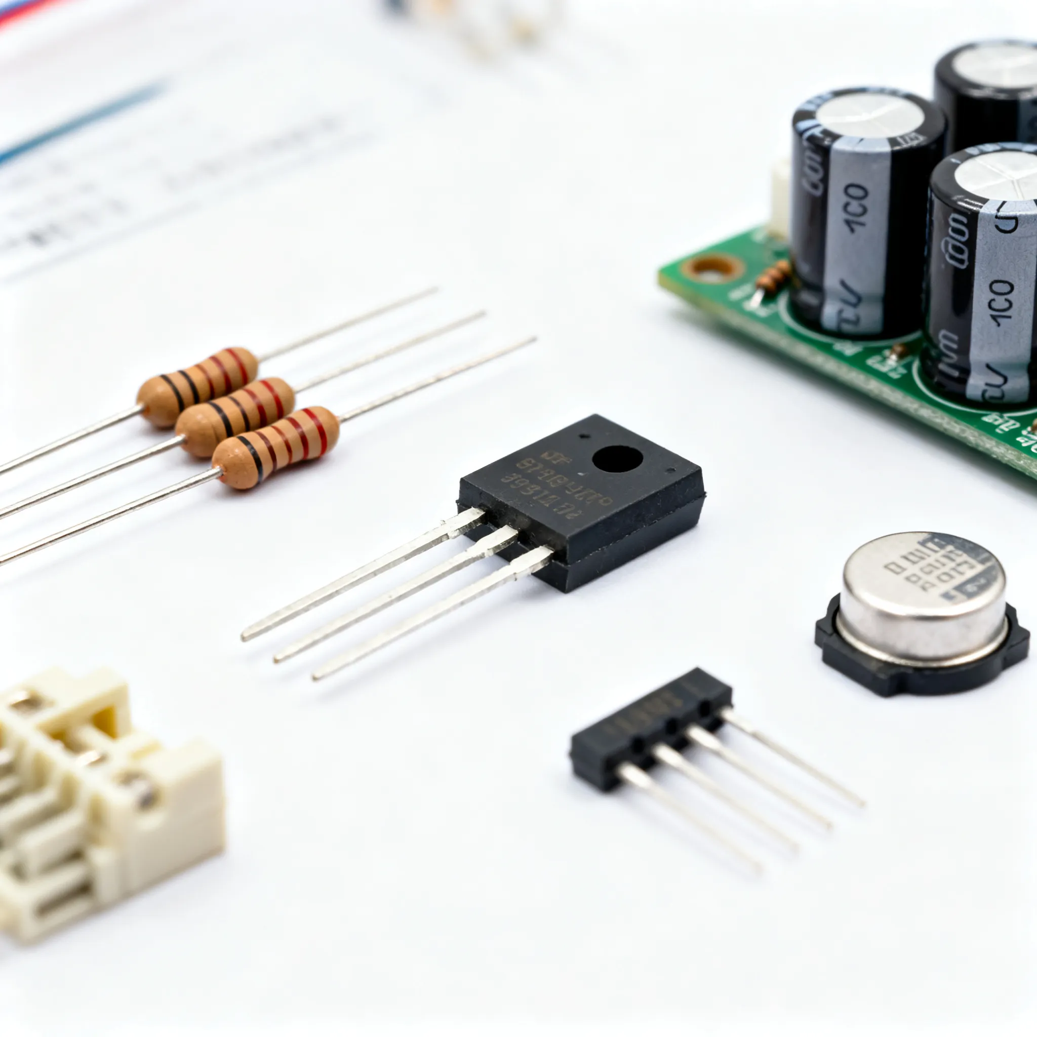
An op-amp integrator circuit uses a simple arrangement of electronic components. The main parts include an operational amplifier, a resistor, and a capacitor. The input signal passes through the resistor and connects to the inverting input of the op-amp. The non-inverting input connects to ground. A capacitor sits in the feedback path, linking the output back to the inverting input. This setup creates a virtual ground at the inverting input. The current entering through the resistor equals the current flowing through the capacitor. Engineers call this arrangement the basic op-amp integrator.
The structure of the op-amp integrator circuit follows Kirchhoff's Current Law. The ideal op-amp integrator assumes infinite input impedance, so no current enters the op-amp itself. The transfer function of the ideal op-amp integrator is v_o/v_i = -1/(sRC). This equation shows that the output voltage is the negative integral of the input voltage over time, scaled by the resistor and capacitor values.
The op-amp integrator circuit acts as a voltage integrator. It accumulates the input voltage and produces an output that changes over time. The frequency response of the op-amp integrator shows infinite gain at DC and a decrease of 20 dB per decade as frequency increases. This matches the expected behavior of an ideal integrator circuit.
Theory
The theory behind the op-amp integrator circuit comes from basic electrical laws. When a voltage signal enters the circuit, it passes through the resistor. The op-amp forces the inverting input to stay at virtual ground. The current through the resistor must flow into the capacitor. The capacitor stores charge, and its voltage changes as it integrates the input current.
The mathematical model for the op-amp integrator uses Kirchhoff’s Current Law at the inverting input. The equation for the output voltage is:
Vout(t) = - (1/RC) ∫ Vin dt + V0
Here, Vout is the output voltage, Vin is the input voltage, R is the resistor, C is the capacitor, and V0 is the initial output voltage. This formula describes the voltage integrator action. The transfer function of voltage integrator is v_o/v_i = -1/(sRC). The op-amp integrator circuit acts as a low-pass filter. Its gain decreases by 20 dB per decade as frequency increases. This is the ac response of integrator circuits.
The op-amp integrator circuit’s performance depends on several factors. High open-loop gain and a large gain bandwidth product (GBP) help the op-amp integrator work well at higher frequencies. Negative feedback stabilizes the gain and improves accuracy. The feedback path, formed by the capacitor, ensures the output tracks the integral of the input. The op-amp integrator circuit’s frequency response, input and output impedance, and bandwidth all affect its performance.
Engineers often use specific resistor and capacitor values to set the integration rate. For example, using R = 10 kΩ and C = 0.1 μF with a TLV9002 opamp shows clear integration behavior. The output voltage changes smoothly as the input signal is integrated over time. The dc characteristics of integrator circuits show that the output drifts if the input has a small offset. The transient response of integrator circuits shows how quickly the output reacts to changes in the input.
Ideal vs. Real Behavior
The ideal op-amp integrator assumes perfect components. In this model, the op-amp has infinite gain, infinite input impedance, and zero output impedance. The output voltage is always the exact negative integral of the input voltage. The ideal op-amp integrator never drifts or saturates. The feedback path works perfectly, and the circuit responds instantly to changes in the input.
In real life, the op-amp integrator circuit behaves differently. Real op-amps have limited gain and bandwidth. The input offset voltage, bias currents, and capacitor leakage cause errors. The output may drift over time, even with no input signal. This drift can push the output into saturation, where it cannot change further. The performance of the op-amp integrator depends on the quality of the op-amp, the resistor, and the capacitor.
To improve real-world performance, engineers add a resistor in parallel with the feedback capacitor. This resistor limits the low-frequency gain and prevents the output from drifting too far. Sometimes, a resistor in series with the capacitor helps reduce the effects of bias currents and improves high-frequency response. The op-amp integrator circuit’s stability and accuracy depend on careful component selection and circuit design.
Tip: Always check the gain bandwidth product and input offset voltage when choosing an opamp for integrator circuits. High GBP and low offset improve the accuracy and stability of the voltage integrator.
The op-amp integrator circuit remains a key building block in analog electronics. Its ability to perform mathematical integration, combined with careful feedback design, makes it useful in many applications. Understanding the differences between the ideal op-amp integrator and real circuits helps engineers design reliable systems.
Integrator Circuits in Applications
Analog Signal Processing
Engineers use integrator circuits in many analog signal processing applications. The voltage integrator can convert a square wave input into a triangle wave output. This function helps shape signals in audio equipment and communication devices. In analog computers, the integrator forms the core of mathematical operations, such as solving differential equations. The circuit accumulates the input voltage over time, which allows it to filter out high-frequency noise. Many signal processing applications rely on the integrator to smooth signals and extract useful information.
Waveform Generation
The integrator plays a key role in generating different waveforms. When a voltage integrator receives a step input, it produces a ramp output. This property is useful in function generators and oscillators. The table below shows how statistical and experimental evidence supports the use of integrators in waveform generation:
|
Evidence Type |
Description |
Quantitative Details |
|---|---|---|
|
Correlation Coefficients |
Model predictions match experimental waveform features |
|
|
Statistical Significance |
Behavioral changes under stimulus validated statistically |
p-values < 0.001 |
|
Integration Time Constant |
Model fitting reveals temporal integration characteristics |
Time constant ~5 seconds |
|
Model Comparison |
Bounded leaky integrator models outperform others |
Non-leaky models fail to capture memory decay |
|
Behavioral Agreement |
Experimental data matches integrator model predictions |
Response delay and accuracy patterns consistent |
-
Motion pulse experiments show integrator variable dynamics matching behavior.
-
Response delay decreases and accuracy increases with stimulus coherence.
-
Memory of motion pulses lasts several seconds, supporting temporal integration.
These results confirm that the integrator circuit can accurately generate and shape waveforms for many applications.
Control Systems
Control systems depend on the integrator to maintain stability and accuracy. The voltage integrator helps regulate feedback in industrial automation, robotics, and automotive systems. The integrated circuits market is growing at a rate of about 13% per year, with analog ICs dominating because of their use in amplifiers, oscillators, and filters. Application-specific ICs offer advantages in speed and reliability for control systems. Major companies like Analog Devices and Texas Instruments continue to innovate in this area.
-
The industrial segment is projected to have the highest growth due to ASICs reducing failure rates.
-
Growth drivers include programmable timers, microcontrollers, and thermal controllers.
-
Control systems are a key application area for integrated circuits, especially in automotive and industrial automation.
Measurement and Memory
The integrator stores and accumulates voltage, making it valuable in measurement and memory applications. In instrumentation, the voltage integrator tracks changes in sensor signals over time. This function allows precise measurement of physical quantities, such as acceleration or flow. The integrator also appears in analog-to-digital converters, where it helps convert analog signals into digital data. Applications of opamp integrator circuits include sample-and-hold circuits and memory elements in analog computers. The ability to store voltage for several seconds, as shown in behavioral experiments, highlights the importance of the integrator in memory-related applications.
Note: The voltage integrator’s ability to accumulate and store voltage makes it essential for both measurement and memory functions in analog systems.
Design Considerations for Integrator Circuits
Component Selection
Engineers select resistors, capacitors, and op-amps carefully to achieve high accuracy in an op-amp integrator circuit. The resistor and capacitor values set the integration rate and time constant. The table below shows important parameters for these components:
|
Parameter |
Formula (Charging) |
Formula (Discharging) |
Description |
|---|---|---|---|
|
Capacitor Voltage |
Vc(t) = V₀(1 - e^(-t/RC)) |
Vc(t) = V₀ * e^(-t/RC) |
Voltage across the capacitor at time t, where V₀ is the source or initial voltage. |
|
Capacitor Current |
Ic(t) = (V₀/R) * e^(-t/RC) |
Ic(t) = -(V₀/R) * e^(-t/RC) |
Current flowing into or out of the capacitor at time t. |
|
Time Constant (τ) |
τ = RC |
τ = RC |
Time for voltage/current to reach ~63.2% of final value during charging or decay to 36.8%. |
Polyester capacitors with less than 5% tolerance and resistors with ±0.1% tolerance help maintain accuracy. Engineers often add a high-value resistor in parallel with the feedback capacitor to limit DC gain and stabilize the circuit. Op-amps like the TLV9002, with low input bias current and offset voltage, improve performance.
Stability
Stability in an op-amp integrator depends on feedback and component choices. MATLAB simulations show that integrator-based controllers keep stable operation under changing loads. The controller adapts to load changes and manages reactive power, keeping voltage and frequency steady. Even with grid disturbances or zero solar input, the op-amp integrator maintains system stability.
Frequency Response
Engineers measure the frequency response of an op-amp integrator by applying a swept sine wave and recording output amplitude and phase. Bode plots display gain and phase versus frequency. The op-amp integrator shows a -20 dB per decade gain roll-off and a phase shift toward -90°. The -3 dB point marks the bandwidth limit, which helps engineers understand circuit performance across frequencies.
Error Sources
Common error sources in an op-amp integrator include input bias current, offset voltage, and drift. These errors can cause the output to drift or saturate. Engineers use low-drift op-amps and stable capacitors to reduce these effects. Compensation resistors and proper grounding also help. Some designs use a switch to reset the feedback capacitor and prevent drift.
Calculations
Accurate design calculations ensure the op-amp integrator meets performance goals. For example, with a 1 V peak sine wave at 5 kHz, the output amplitude calculates to about 0.318 V with a 90° phase lead. Simulations confirm this result, showing that theoretical and practical integrator circuits match closely when designed correctly.
Tip: Always check component tolerances and op-amp specifications to maximize accuracy and circuit performance.
Integrator circuits help engineers process signals, generate waveforms, and control systems. Understanding both the theory and real-world behavior leads to better designs. Careful component selection and attention to stability improve performance.
Quick-Reference Checklist for Integrator Circuit Design:
-
Use precise resistors (±0.1% tolerance)
-
Choose stable capacitors (low temperature drift, <5% tolerance)
-
Select op-amps with high gain and low noise
-
Add a feedback resistor for stability
-
Check for offset voltage and bias current
A strong grasp of these basics ensures reliable and effective integrator circuits.
FAQ
What is the main function of integrator circuits?
Integrator circuits perform mathematical integration on input signals. They produce an output that represents the accumulated value of the input over time. Engineers use them in analog systems for signal processing applications, waveform generation, and control.
How does an op-amp integrator circuit work?
An op-amp integrator circuit uses a resistor and capacitor with an op-amp. The input passes through the resistor, and the capacitor connects in the feedback path. The output voltage changes based on the integral of the input, following the transfer function of the ideal op-amp integrator.
What are some common applications of opamp integrator circuits?
Applications of opamp integrator circuits include analog computers, waveform generators, and control systems. Engineers also use them in measurement devices and memory elements. These circuits help process signals and store information in many analog applications.
How do ideal and practical integrator circuits differ?
The ideal integrator circuit assumes perfect components and no errors. Practical integrator circuits experience drift, offset, and limited performance due to real-world factors. Engineers improve circuit performance by careful design and adding feedback resistors.
Why is component selection important in circuit design?
Component selection affects accuracy, stability, and circuit performance. Choosing precise resistors, stable capacitors, and a suitable opamp ensures the voltage integrator works as intended. Good circuit design reduces errors and improves the response of the integrator.