

3 Input NAND Truth Table and Its Logic in 2025
A 3-input nand gate is a digital logic gate that lets you combine three binary signals using the nand operation. You see its

A 3-input nand gate is a digital logic gate that lets you combine three binary signals using the nand operation. You see its output turn low only when all three inputs are high. The 3 input nand truth table shows this unique pattern: the output stays high unless every input is one. Engineers use the 3-input nand for complex boolean operations. The nand gate stands out for its universal property, letting you create any boolean function with just nand gates. This makes your circuit designs more flexible and cost-effective. You can always rely on the truth table and boolean logic to predict how the 3 input nand truth table behaves.
Key Takeaways
- A 3-input NAND gate outputs 1 unless all three inputs are 1, making it the opposite of an AND gate.
- The truth table for a 3-input NAND gate has eight input combinations, with output 0 only when all inputs are high.
- You can express the NAND gate logic as (A · B · C)' or as A' + B' + C' using De Morgan's theorem.
- NAND gates are universal; you can build any logic gate or function using only NAND gates, simplifying circuit design.
- 3-input NAND gates are widely used in real circuits like alarms and control systems, offering flexibility and cost savings.
3 Input NAND Truth Table

Input Combinations
When you work with a 3-input nand gate, you need to understand all the possible ways you can set the inputs. Each input can be either 0 (LOW) or 1 (HIGH). With three inputs, you get eight different input combinations. You can see these combinations in the logic gate truth table below. This table helps you fill out the truth table for any 3-input nand circuit.
| A | B | C | Output |
|---|---|---|---|
| 0 | 0 | 0 | 1 |
| 0 | 0 | 1 | 1 |
| 0 | 1 | 0 | 1 |
| 0 | 1 | 1 | 1 |
| 1 | 0 | 0 | 1 |
| 1 | 0 | 1 | 1 |
| 1 | 1 | 0 | 1 |
| 1 | 1 | 1 | 0 |
You can use this table to create a truth table for any 3-input nand circuit. Each row shows a different input combination. The output column tells you what happens for each set of inputs. If you look at the digital logic truth tables for other gates, you will notice that the 3 input nand truth table has a unique pattern.
Tip: You can remember the pattern by noting that the output is always 1 except when all three inputs are 1.
Here is a chart that shows the truth table outputs for all input combinations:
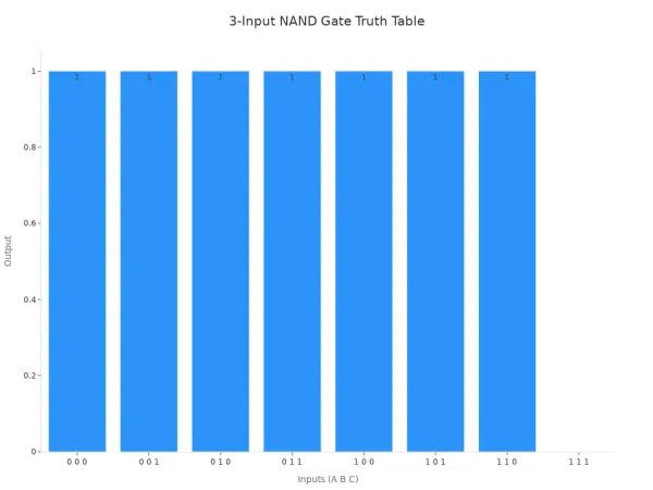
Output Pattern
You will notice a clear output pattern in the 3 input nand truth table. The output stays HIGH (1) for every input combination except when all three inputs are HIGH (1). Only when A, B, and C are all set to 1 does the output drop to LOW (0). This behavior matches the basic rule for a nand gate: the output is the opposite of the AND gate. If you compare the 3-input nand to other gates, you will see that the AND gate only gives a HIGH output when all inputs are HIGH, but the nand gate does the reverse.
Let’s look at how the output pattern compares to other gates:
| Logic Gate | Output Condition for High (1) | Output Condition for Low (0) |
|---|---|---|
| AND | All inputs are high (1) | Any input is low (0) |
| NAND | Any input is low (0) | All inputs are high (1) |
| OR | Any input is high (1) | All inputs are low (0) |
| NOR | All inputs are low (0) | Any input is high (1) |
| XOR | Inputs differ | Inputs are the same |
You can see that the 3-input nand is special because it inverts the AND function. This makes the 3 input nand truth table very useful in boolean logic. When you design circuits, you often use the 3-input nand to build more complex boolean functions. You can rely on this output pattern to predict how your circuit will behave.
If you want to fill out the truth table for your own project, just remember: the output is 1 for every input combination except when all inputs are 1. This simple rule helps you understand and use the 3-input nand in many digital circuits.
NAND Gate Logic

Boolean Expression
You can describe the logic of a 3-input nand gate using a simple boolean expression. This expression shows how the gate processes its three inputs. Here is how you can break it down:
- Start with the AND operation for three inputs: A, B, and C. In boolean terms, this is written as A · B · C.
- The nand operation inverts the result of the AND. You show this by adding a prime symbol (') to the expression: (A · B · C)'.
- This means the output is high unless all three inputs are high.
- You can use De Morgan's theorem to rewrite the expression. The theorem says that the negation of an AND operation equals the OR of the negations: (A · B · C)' = A' + B' + C'.
- You can use this form to simplify circuits or to convert other boolean expressions into a form that uses only the nand operation.
Note: You can use Karnaugh maps and boolean algebra to simplify more complex expressions and build circuits using only nand gates.
Logic Operation
When you use a 3-input nand gate, you perform a special logic operation. The gate checks all three inputs. If any input is low, the output stays high. Only when all three inputs are high does the output drop to low. This behavior is the opposite of the AND gate. The AND gate gives a high output only when all inputs are high. The nand gate inverts this result.
You can think of the nand operation as two steps. First, the gate performs the AND operation on the inputs. Then, it applies a NOT operation to the result. This is why the output is the inverse of the AND gate. You can use De Morgan's laws to understand this relationship. The laws show that you can build any logic function using only nand gates. This makes the nand gate a universal building block in digital circuits.
If you want to create a NOT operation, you can connect both inputs of a 2-input nand gate to the same signal. For more complex boolean functions, you can combine several nand gates. This flexibility helps you design efficient digital systems using just one type of gate.
3-Input NAND Applications
Universal Gate
You can use the nand gate as a universal building block in digital electronics. This means you can create any other logic gate using only nand gates. The reason for this is simple: the nand gate can mimic the functions of AND, OR, NOR, XOR, and NOT gates. You achieve this by connecting multiple nand gates in specific ways. For example, if you connect all inputs of a nand gate together, you get a NOT gate. If you combine several nand gates, you can build AND and OR gates by following rules from boolean algebra and DeMorgan's Theorem.
You can design any boolean function using only nand gates. This gives you flexibility and makes your circuit designs easier to manage.
Here are some benefits of using nand gates as universal gates:
- You need fewer types of components, which makes your circuit simpler.
- You save money because you use fewer different gates.
- You can build reliable circuits since you use the same type of gate throughout.
- You can easily integrate nand gates into complex digital systems.
When you work with 3-input nand gates, you can combine them to create multi-input logic functions. You can also use them to build basic gates like AND, OR, and NOT. This makes the nand gate a powerful tool in digital logic design.
Circuit Uses
You will find 3-input nand gates in many digital circuits. Common ICs include the 74LS10 for TTL technology and the CD4023 for CMOS technology. These chips usually have three separate 3-input nand gates inside a single package. You can use these gates to create multi-input logic functions without needing extra components.
Here are some practical uses for 3-input nand gates:
- You can build alarm circuits, freezer warning buzzers, and automatic temperature control systems.
- You can analyze sensor status for doors and windows in security systems.
- You can convert a 3-input nand gate into a simple inverter by tying all inputs together.
- You can simplify your circuit design by using fewer gates for multi-input logic.
| Application Category | Examples / Devices / ICs |
|---|---|
| Real-world Applications | Alarm circuits, freezer buzzers, temperature control, sensor analysis, burglar alarms |
| 3-input NAND Gate ICs | TTL: 74LS10, CMOS: CD4023 |
You can test and verify the operation of a 3-input nand gate using a logic training board. This board lets you apply all possible input combinations and observe the output. You can confirm that the gate works as expected by checking its output against the truth table.
Tip: When you use 3-input nand gates in TTL circuits, you can tie unused inputs to ground to reduce power use and improve stability.
You can rely on the nand gate to help you build efficient and reliable digital systems. Its universal property and wide use in TTL and CMOS circuits make it essential for modern electronics.
You gain a strong foundation in digital electronics when you understand the 3-input nand truth table. This knowledge helps you design circuits, solve problems, and build reliable systems.
- The nand gate lets you create any logic function, making your designs flexible and efficient.
- You can use the truth table to check outputs and find faults quickly.
- Modern electronics rely on nand gates for memory, processors, and new technologies like optical computing.
Mastering nand logic prepares you for future advances in digital systems.
FAQ
What is the main function of a 3-input nand gate?
You use a 3-input nand gate to combine three signals. The output stays high unless all inputs are high. This logic gate helps you build complex circuits using simple rules from the 3 input nand truth table.
How do you create a truth table for a 3-input nand?
You list every input combination for A, B, and C. For each row, you apply the nand operation. The output is high except when all inputs are high. This process helps you fill out the truth table quickly.
Why is the nand gate called a universal gate?
You can build any digital logic gate using only nand gates. This universal property lets you design all types of circuits. You use the logic gate truth table and boolean rules to combine nand gates for different functions.
How does the output pattern of a 3-input nand compare to other gates?
The 3-input nand gives a high output for every input combination except when all inputs are high. Other digital logic truth tables, like AND or OR, show different output patterns. You can use these differences to design circuits that fit your needs.
Where do you use 3-input nand gates in real circuits?
You find 3-input nand gates in alarm systems, control panels, and sensor circuits. These gates help you simplify designs. You can use them in TTL and CMOS chips to handle many logic tasks with fewer components.


