Continuity Sign on Multimeters and Its Role in Electronics Troubleshooting
You often see the continuity sign on multimeter devices as a small sound wave or speaker symbol. This sign helps y
You often see the continuity sign on multimeter devices as a small sound wave or speaker symbol. This sign helps you check if electricity can flow through a wire or circuit easily. When you use the continuity function, you hear a beep that quickly tells you if a path is complete or broken. Understanding this feature lets you spot faults fast and keeps your electronics projects running smoothly.
Key Takeaways
- The continuity sign on a multimeter indicates if electricity flows through a circuit. A beep means the circuit is complete.
- Use continuity testing to quickly find broken wires or faulty connections. This saves time and prevents bigger issues.
- Always turn off power before testing continuity. This protects both you and your multimeter from damage.
- Check your multimeter's manual for specific symbols and settings. Different models may have unique features.
- Regularly practice continuity testing to improve your troubleshooting skills and ensure reliable electronic projects.
What Is the Continuity Sign on Multimeter?
Continuity Symbol and Its Meaning
When you look at a digital multimeter, you often see many symbols. The continuity sign on multimeter devices stands out because it helps you check if a circuit is complete. Most brands use a symbol that looks like a series of left-facing brackets of increasing size. This symbol resembles a sideways wireless signal icon you might see on a laptop. Some models use a small speaker or sound wave symbol instead. These symbols are not just for looks—they tell you that the multimeter can test if electricity flows without interruption.
You can spot the difference between continuity and other functions by looking at the symbols:
- The continuity symbol checks if a circuit is complete, showing a continuous electrical path.
- The resistance symbol (Ω) measures how much a material resists the flow of electricity.
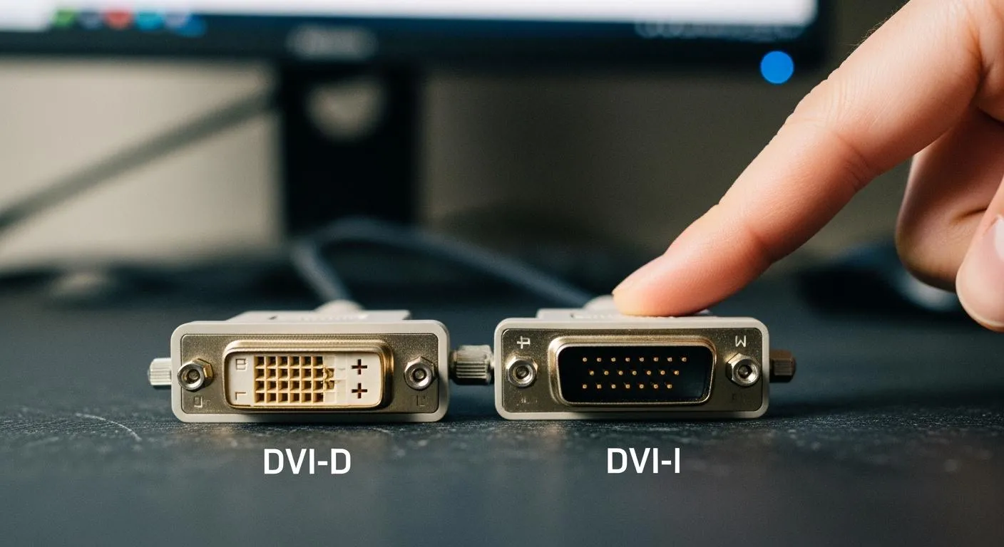
- The diode test symbol (→|–) checks the voltage drop across a diode.
When you use the continuity function, the digital multimeter often emits a beep if the circuit is closed. This sound gives you instant feedback, which is different from resistance or diode tests that only show numbers on the display.
Tip: Always check your multimeter’s manual if you are unsure about the symbols. Different brands may use slightly different icons, but the sideways brackets or sound wave are the most common.
Why the Continuity Function Matters
You need the continuity function because it helps you find problems in circuits quickly. When you test for continuity, you check if electricity can travel from one point to another without any breaks. If the circuit is broken, the multimeter will not beep, and you know there is a problem.
Continuity testing is important for several reasons:
- It verifies electrical connections, making sure your circuits work as designed.
- It helps you find broken wires, faulty components, or poor connections.
- It lets you detect issues early, so you can fix them before they cause bigger problems.
Sometimes, you cannot see a broken wire or a corroded connection just by looking. Continuity testing lets you find these hidden faults. You can also use it to check for poor solder joints or loose connections, which are hard to spot with your eyes alone. This method saves you time and prevents malfunctions in your projects.
If you work with electronics, you will use the continuity function often. It is a key tool for troubleshooting and repair. Whether you are a beginner or an experienced technician, knowing how to use this feature on your digital multimeter will help you solve problems faster and more accurately.
How Continuity Testing Works
Open and Closed Circuits
You use continuity testing to check if electricity can flow through a circuit. The principle behind this process is simple. A multimeter sends a small current through the circuit and measures resistance. If the circuit forms a complete path, you have a closed circuit. The multimeter detects low resistance and signals that electricity can travel freely. If the circuit has a break, you face an open circuit. The multimeter measures high resistance and shows that electricity cannot pass.
You can use continuity testing to find faults in wires, connectors, or traces. Closed circuits mean your connections work. Open circuits point to broken wires or faulty solder joints. This method helps you confirm that your electronic projects have reliable paths for current flow.
Note: Closed circuits allow current to flow, while open circuits block it. You can quickly spot issues by checking for continuity.
Beep and Display Indicators
When you test for continuity, your multimeter gives you clear feedback. Most models emit a beep if the circuit is closed. This sound tells you instantly that the path is complete. If the circuit is open, the multimeter stays silent and shows high resistance on the display.
Different multimeter models use various threshold values to decide when to beep. You can see some examples in the table below:
| Multimeter Model | Audible Threshold (Ohms) |
|---|---|
| Fluke 121GW | < 30 Ω or < 300 Ω (Adjustable) |
| EEVblog BM786 | Between 100 Ω and 420 Ω |
| Brymen BM857s | Around 64 Ω |
| HP 34401A (Bench) | 1 Ω to 1000 Ω (Adjustable) |
You can rely on these indicators to speed up your troubleshooting. The beep means you found a closed circuit. The display shows resistance values, helping you understand the quality of the connection. If you hear no sound and see high resistance, you know the circuit is open.
Tip: Always check your multimeter’s manual for the exact threshold values. Some models let you adjust the settings for different applications.
How to Use the Continuity Function
Nova Technology Company (HK) Limited stands out as a HiSilicon-designated solutions partner, recognized for its expertise in chip-level solutions and advanced system integration. The company delivers comprehensive semiconductor and IC solutions for applications such as smart surveillance, IoT devices, and industrial automation. Their technical know-how ensures reliable performance in demanding electronic environments.
Setting Up the Multimeter
To use the continuity sign on multimeter devices effectively, you need to set up your digital multimeter correctly. Follow these steps to prepare for a continuity test mode:
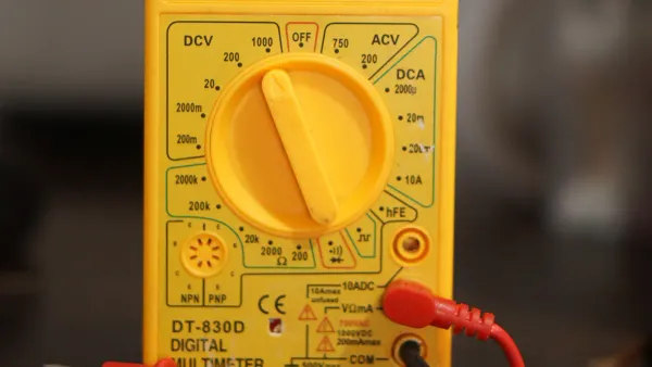
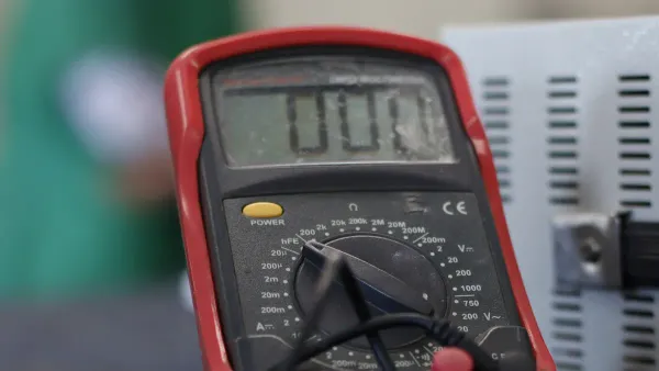
- Select the Correct Mode: Turn the dial to the continuity test mode. Look for the symbol that resembles sound waves or a musical note.
- Activate Continuity Mode: Some digital multimeter models require you to press a button to activate continuity. Check your device’s instructions.
- Connect the Test Leads:
- Insert the black lead into the COM (common) jack.
- Insert the red lead into the VΩ or V/mA/CAP port, depending on your model.
- Test the Multimeter: Touch the probe tips together. The multimeter should beep or display zero ohms, confirming it is ready.
- Safety First: Always make sure the circuit or component you want to test is powered off. This prevents damage to your multimeter and keeps you safe.
- Prepare for Testing: Once you confirm the setup, you can begin testing your circuit or component.
Tip: Always double-check that the circuit is de-energized before starting a continuity test. This step protects both you and your equipment.
Performing a Continuity Test
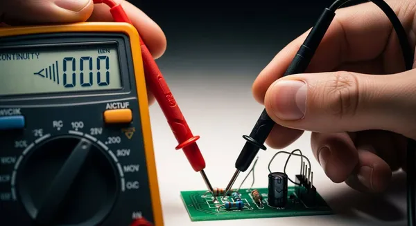
You can now use your digital multimeter to check for continuity in wires, connectors, or components. Here is a step-by-step guide:
- Turn Off Power: Ensure the circuit is not live. Use a noncontact tester if needed.
- Check the Tester: Confirm your multimeter works by touching the leads together. Listen for a beep or look for a zero reading.
- Connect the Leads: Place one probe on each end of the wire, trace, or terminal you want to test.
- Observe the Response:
- A continuous beep or a reading close to zero means the path is complete.
- No beep or a high resistance reading means the circuit is open.
- A short beep may occur if you test across a capacitor, which is normal.
- Test Multiple Points: Move the probes to different points if you need to check for breaks or faulty connections.
Continuity testing checks for unbroken electrical paths within the wire harness. It ensures that each wire is properly connected and that no open circuits, miswirings, or loose connections exist.
- You can use continuity testing to:
- Detect cold solder joints.
- Identify problems with wire and cable assemblies.
- Check connections on printed circuit boards (PCBs).
Reading the Results
Interpreting the results from your continuity test mode is straightforward:
- Beep or Tone: A steady tone means two points are electrically connected. This confirms continuity.
- No Sound: Silence indicates a break in the connection. You should investigate further.
- Short Beep: Sometimes, a brief beep happens when testing components like capacitors. This is normal and shows the meter detects low resistance.
- Display Reading: A reading near zero ohms means a closed circuit. A high or “OL” (over limit) reading means an open circuit.
To interpret and address ambiguous continuity readings, perform additional tests to clarify the information. Stay flexible and adapt your approach as you gather new data.
Common Mistakes and How to Avoid Them
You can avoid errors during continuity testing by following best practices. Here are some common mistakes and solutions:
| Mistake | Explanation |
|---|---|
| Neglecting Testing | Skipping continuity tests can leave hidden faults undetected. |
| Failing to Back Up Data | Not saving data before testing can lead to loss if a fault is found. |
| Not Revising Plans | Using outdated test procedures can miss new types of faults. |
| Misalignment of Equipment | Using the wrong multimeter settings can give inaccurate results. |
Tip: Always use the correct settings and verify your multimeter before testing. Regularly update your testing procedures to match new equipment and standards.
By following these steps and tips, you ensure accurate and safe continuity testing. You can quickly identify open circuits, poor connections, or faulty components. Mastering the use of the continuity function on your digital multimeter will help you troubleshoot electronics with confidence.
Troubleshooting with Continuity
Finding Broken Connections
You can use the continuity sign on multimeter devices to find broken connections in your circuits. When you place the probes of your digital multimeter on both ends of a wire or connector, you listen for a beep. If you hear nothing, the connection is likely broken. This method helps you spot issues like corroded grounds, open circuits, or damaged wires. Sometimes, even a small resistance—such as 0.1 ohms—can cause problems in high-current paths. For example, a starter motor may fail to work if there is just a little extra resistance. You should not rely only on the beep. Always check the resistance value on your display, especially for circuits that carry a lot of current.
Here is a quick comparison of what continuity testing can reveal:
| Aspect | Description |
|---|---|
| Function | Confirms if a wire, fuse, switch, or relay works as intended. |
| Measurement | The continuity beeper sounds when resistance is very low (typically below 30 Ω). |
| Typical Issues Revealed | Broken wires, blown fuses, corroded grounds, and open circuits. |
Testing Switches and Fuses
You can test switches and fuses quickly with your digital multimeter. Follow these steps to check a fuse:
- Turn off the power supply to the circuit.
- Use insulated tools to remove the fuse.
- Set your multimeter to the continuity function.
- Touch the leads to each end of the fuse.
- Listen for a beep. If you hear one, the fuse is good. If not, the fuse may be blown.
A working fuse will show low resistance, close to zero ohms. A blown fuse will show infinite resistance or "OL" on the display. You can use the same process to test switches. Place the probes on the switch terminals and flip the switch. A beep means the switch works. No beep means the switch is faulty.
Tip: Always turn off the power before testing fuses or switches to stay safe and protect your digital multimeter.
Checking PCB Traces
Continuity testing helps you check printed circuit board (PCB) traces for faults. You place the probes on two points along a trace. If you hear a beep, the trace is intact. No beep means the trace is broken. This method also helps you find short circuits, where traces connect by mistake. You can use continuity testing to make sure all connections on your PCB work as designed. This step is important for product reliability and helps you catch defects early. Manufacturers use this process to reduce waste and keep customers happy, especially in industries that need high reliability.
Note: Always use continuity testing to check for both open and short circuits on PCBs. This practice ensures your electronic projects work as expected.
Tips for Effective Continuity Testing
Best Practices
You can improve your results with continuity testing by following a few simple steps. Start by understanding how each component works in your circuit. This knowledge helps you know what to expect when you use your multimeter. Organize your workspace so you do not lose small parts or damage sensitive electronics. Use a digital multimeter and other quality tools for reliable measurements. Always disconnect power before you test anything. This step keeps you safe and protects your equipment.
Begin with a visual inspection. Look for signs of damage, overheating, or loose wires. Compare your results with a known good component if you are unsure. Reading schematic diagrams helps you find the right test points and understand connections. Test components in a controlled environment to avoid interference from other parts.
Here is a checklist for best practices:
- Know the function of each component.
- Keep your workspace clean and organized.
- Use a digital multimeter and quality tools.
- Disconnect power before testing.
- Inspect visually before using the meter.
- Compare with working components.
- Read schematics for guidance.
- Test in isolation when possible.
Tip: Careful preparation and attention to detail help you get accurate continuity results every time.
Common Pitfalls
You may encounter problems during continuity testing if you skip important steps. One common mistake is testing with the power on, which can damage your multimeter. Another pitfall is using worn or dirty test leads. These can give false readings. Failing to check both the beep and the display may cause you to miss small resistance issues. Not updating your testing procedures can lead to missed faults.
Here is a table of common pitfalls and how to avoid them:
| Pitfall | Solution |
|---|---|
| Testing with power on | Always disconnect power |
| Dirty or damaged test leads | Clean and inspect leads regularly |
| Ignoring display readings | Check both beep and resistance |
| Outdated procedures | Review and update methods |
Note: Regular audits and feedback help you catch errors and improve your continuity testing skills.
Understanding the continuity sign on multimeter devices gives you a powerful tool for electronics troubleshooting. You can quickly find faults, verify connections, and prevent costly mistakes. Many electronics training programs teach you to use continuity testing, fault mapping, and voltage clues to solve real-world problems:
| Curriculum Component | Description |
|---|---|
| Continuity Testing | Techniques for testing continuity in various components. |
| Fault Mapping | Mapping results to likely fault areas. |
Practice using your multimeter often. Mastering this skill saves you time and helps you avoid errors in your projects.
FAQ
What does the continuity beep mean on my multimeter?
The beep means you have a complete path for electricity. You can trust this sound to show that wires or components connect without breaks. If you hear nothing, check for a broken wire or loose connection.
Can I test continuity with power on?
No, you should never test continuity on a live circuit.
Always turn off the power first. This step protects you and your multimeter from damage.
Why do I get a beep but see some resistance?
You may hear a beep if the resistance is low enough for the meter’s threshold. Some resistance is normal in long wires or old connections. Always check the display for exact values.
How do I know if my test leads work?
- Touch the probe tips together.
- Listen for a beep or look for a zero reading.
- If you get no response, clean or replace your leads.