

Advanced RJ45 PCB Design Guide for Modern Ethernet
Your first decision in any modern Ethernet PCB design is simple: use the T568B pinout standard. This choice sets the foundat
Your first decision in any modern Ethernet PCB design is simple: use the T568B pinout standard. This choice sets the foundation for a reliable product. A surprising amount of network failures, sometimes up to 70%, trace back to physical layer issues like faulty RJ45 connectors or cabling on the PCB. To avoid these problems, you must master four key areas. This guide focuses on the essentials for your RJ45 PCB: the correct pinout, proper magnetics integration, robust Power over Ethernet (PoE) implementation, and effective protection circuits. Getting these right on your PCB is critical for any Ethernet device. What is Ethernet RJ45? It's the gateway to your device's connectivity, and its success depends on your PCB design.
Key Takeaways
- Always use the T568B wiring standard for your RJ45 connector. This helps your device connect correctly to most networks.
- Use special parts called magnetics. They keep your device safe from electricity and block noise. Make sure to leave a clear space, called an 'isolation moat,' on your circuit board around them.
- If you use Power over Ethernet (PoE), pick strong parts that can handle the extra power. Design your circuit board to spread out heat so parts do not get too hot.
- Protect your RJ45 connector from static electricity and other interference. Place special diodes close to the connector to stop static, and connect the connector's metal shield to ground.
What is Ethernet RJ45 and Why is it Critical?
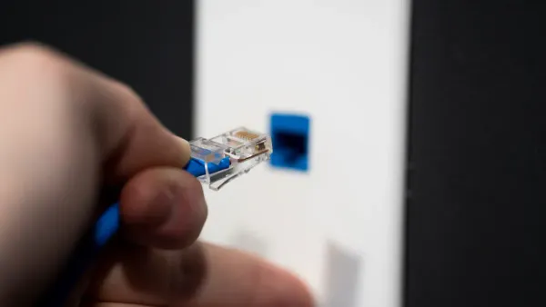
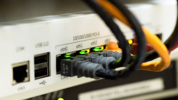
What is Ethernet RJ45? The RJ45 connector is the physical interface for nearly every wired network connection. You see this familiar connector on laptops, routers, and servers. It is the gateway that allows your device to send and receive data over an Ethernet network. The success of your product's network communication depends heavily on the design of this single component. A well-designed RJ45 implementation ensures a stable and fast network link.
The Role of RJ45 in Modern Data Systems
The RJ45 connector is more than just a simple plug. It is a highly engineered component designed for high-speed data transmission. Its design is critical for maintaining signal integrity in today's demanding network environments. For instance, companies like Nova Technology Company (HK) Limited, a HiSilicon-designated solutions partner, rely on robust physical layer components for their advanced data systems. The RJ45 connector is a key part of the Ethernet protocol. Key features that make the RJ45 connector ideal for high-speed data include:
- 8-Pin Configuration: The connector houses eight pins that accommodate four twisted wire pairs, essential for high-speed Ethernet data.
- High-Speed Capability: It supports various Ethernet standards, enabling speeds up to 10 Gbps for rapid data transfer.
- Shielding Options: A comprehensive shielding system is available to protect signals from electromagnetic interference (EMI), ensuring reliable RJ45 connections.
What is Ethernet RJ45? It is the standardized connector that makes our modern digital world possible. Your design must respect its capabilities to build a reliable network product.
Understanding Auto MDI-X and its Impact
In the past, you needed two different types of Ethernet cables. A straight-through cable connected a device to a network switch, while a crossover cable connected two similar devices. Using the wrong cable would cause the network link to fail. This created confusion and installation errors. What is Ethernet RJ45's solution to this? The answer is Auto MDI-X.
Auto MDI-X (Automatic Medium-Dependent Interface Crossover) is a feature in modern Ethernet ports. It automatically detects the type of cable you are using. The Ethernet port then swaps its transmit and receive pairs internally to make the connection work. This technology eliminates the need for crossover cables entirely.
Design Tip: Thanks to Auto MDI-X, you no longer need to worry about crossover connections at the hardware level. You can design every Ethernet port using the standard T568B pinout, simplifying your PCB layout and making your product easier for end-users to install on any network. What is Ethernet RJ45? It's a smart connector that simplifies network setup.
This feature makes any network more robust and user-friendly. What is Ethernet RJ45's biggest advantage for you? It simplifies your design process for the Ethernet port.
Understanding the RJ45 Pinout: T568B Standard
Choosing the T568B standard is your first step toward a compliant and reliable Ethernet design. This standard dictates the specific wiring arrangement within an RJ45 connector, ensuring your product communicates correctly with the broader network. A consistent wiring scheme is the backbone of a stable physical network layer.
The T568B RJ45 Pinout Standard
The T568B standard is the dominant wiring scheme for new commercial products and network installations in the United States and worldwide. The Telecommunications Industry Association (TIA) defines this standard in its ANSI/TIA-568.2-D documentation. This specification tells you exactly how to match the colored wire pairs in an Ethernet cable to the pins on an RJ45 plug. Following this RJ45 pinout is critical for network compatibility.
For your PCB design, you must map the signals from your Ethernet PHY to the RJ45 connector pins according to this standard. Here is the official T568B wiring configuration:
| Pin | T568B Pair | T568B Color | 10/100BASE-T Signal | 1000BASE-T Signal |
|---|---|---|---|---|
| 1 | 2 | White/Orange Stripe | TX+ | BI_DA+ |
| 2 | 2 | Orange Solid | TX- | BI_DA- |
| 3 | 3 | White/Green Stripe | RX+ | BI_DB+ |
| 4 | 1 | Blue Solid | Not Used | BI_DC+ |
| 5 | 1 | White/Blue Stripe | Not Used | BI_DC- |
| 6 | 3 | Green Solid | RX- | BI_DB- |
| 7 | 4 | White/Brown Stripe | Not Used | BI_DD+ |
| 8 | 4 | Brown Solid | Not Used | BI_DD- |
This table is your blueprint for the RJ45 wiring. You must ensure your schematic and layout connect the correct PHY signals to these RJ45 pins.
T568B Pinout for 10/100/1000BASE-T Ethernet
The function of the RJ45 pins changes depending on the Ethernet speed. Your design must account for these differences, even though the physical wiring remains the same.
-
For 10/100BASE-T Ethernet: This older Ethernet standard uses only two of the four wire pairs.
- Pins 1 and 2 (the orange pair) transmit data (TX+, TX-).
- Pins 3 and 6 (the green pair) receive data (RX+, RX-).
- Pins 4, 5, 7, and 8 are unused for data transmission in this mode.
-
For 1000BASE-T (Gigabit) Ethernet: This modern standard provides a massive speed boost by using all four wire pairs. It employs a sophisticated technique where data travels in both directions on all pairs simultaneously.
- There are no longer separate "transmit" and "receive" pairs.
- Each pair (DA, DB, DC, DD) is a bi-directional data channel.
- This advanced signaling is why Gigabit Ethernet requires high-quality wiring and careful PCB layout to function correctly on a network.
This use of all four pairs for bidirectional data is crucial for achieving gigabit speeds over standard Ethernet wiring. Your design must route all four differential pairs from the PHY to the RJ45 connector to support this functionality.
When to Consider the T568A Legacy Standard
While T568B is the default for new commercial designs, you may encounter situations that require the T568A standard. You should only use T568A wiring for specific compatibility reasons. These cases include:
- Projects for U.S. federal government contracts, which often mandate T568A wiring.
- Residential installation projects where T568A is the existing standard.
- Designs that must maintain backward compatibility with older USOC telephone wiring.
The only difference between the two standards is the position of the orange and green wire pairs.
Design Alert: In T568A wiring, the green pair connects to pins 1 and 2, while the orange pair connects to pins 3 and 6. The blue and brown pairs remain the same. This swap is the only distinction from T568B wiring.
Unless you are designing for one of these specific legacy applications, you should always use the T568B wiring standard. This ensures your product is ready for modern network installation and avoids confusion. Sticking to T568B simplifies the design, manufacturing, and installation process for any Ethernet device.
Integrating Ethernet Magnetics
Ethernet magnetics are essential components in your RJ45 circuit. You cannot design a compliant Ethernet port without them. These small transformers and chokes sit between the Ethernet PHY chip and the RJ45 connector. They perform critical functions that ensure your device communicates reliably and safely. A proper PCB design for your magnetics is just as important as selecting the right component.
Core Functions: Isolation, Noise Rejection, and Impedance Matching
Magnetics serve three primary purposes in every Ethernet design. Understanding these functions helps you appreciate their importance on your PCB.
- Electrical Isolation: The magnetics create a galvanic isolation barrier. This protects your device and the user from dangerous DC voltage differences or electrical surges that can occur between two networked devices. This isolation is a fundamental safety requirement for any Ethernet product.
- Common-Mode Noise Rejection: Ethernet cables act like antennas, picking up noise from the environment. The magnetics, specifically their common-mode chokes, are designed to filter this out. They present a high impedance to unwanted common-mode noise, effectively blocking it. At the same time, they allow the differential Ethernet signal to pass through with very low opposition. This prevents noise picked up on the cable from corrupting the signal or coupling into your PHY and the rest of the PCB.
- Impedance Matching: Ethernet cables have a characteristic impedance of 100Ω. The magnetics help match the impedance of your PHY transceiver to the cable. Proper impedance matching is critical for signal integrity. It prevents signal reflections that can cause data errors and degrade the performance of the Ethernet connection.
Layout Best Practices: The Isolation Moat
The most critical rule for laying out your Ethernet port is to create an "isolation moat" on your PCB. This moat is a physical keep-out area that separates the circuitry on the connector side from the circuitry on the PHY side. You must not run any traces or copper planes across this gap.
This physical separation on the PCB enforces the electrical isolation provided by the magnetics. It creates two distinct ground zones:
- Chassis Ground: The area around the RJ45 connector and its shield. This side is considered "dirty" because it is exposed to external noise and potential ESD events.
- Digital Ground: The area around your PHY and other digital logic. This is your system's "clean" ground.
By creating a void between these two ground planes, you prevent noise from the connector side from "jumping" over to your sensitive digital circuits.
Layout Tip: Your PCB layout software should show a clear physical gap between the connector-side ground plane and the PHY-side ground plane. We recommend including a layout example image in your design documentation to clearly illustrate this isolation moat for review.
Routing 100Ω Differential Pairs
The Ethernet signal travels over four differential pairs. You must route these pairs on your PCB with a controlled impedance of 100Ω to match the cable. Failing to control this impedance will damage your signal integrity. Follow these rules for routing the differential pairs between the magnetics and the RJ45 connector, and between the PHY and the magnetics.
- Maintain Consistent Geometry: Use a uniform trace width and spacing for the entire length of the pair. Your PCB fabricator can help you calculate the correct dimensions for your specific PCB stackup.
- Keep Traces Parallel and Tightly Coupled: The two traces in a pair should run as close together as your design rules allow. This helps them reject noise effectively.
- Use Gentle Curves: Avoid sharp 90-degree bends. Sharp corners change the impedance and can cause signal reflections. Use smooth, curved traces with a large radius instead.
- Ensure a Solid Return Path: Always route differential pairs over a continuous, solid ground plane. Never route them across a split or gap in the ground plane, as this breaks the return path for the signal.
- Use Vias Sparingly: Vias introduce impedance discontinuities. If you must change layers, use vias in symmetrical pairs (one for each trace in the pair) and place them as close together as possible.
Discrete Magnetics vs. Integrated MagJacks
You have two main options for implementing Ethernet magnetics on your PCB: discrete components or an integrated RJ45 connector, often called a "MagJack." Your choice impacts PCB layout, cost, and performance.
Discrete magnetics involve placing separate transformer and choke components on the PCB between the PHY and a basic RJ45 connector.
- Advantages: This approach offers the best performance and flexibility. You can achieve excellent common-mode filtering and nearly eliminate crosstalk with a good PCB layout. It is also easier to repair, as you can replace individual components. This makes discrete magnetics a better choice for high-reliability applications.
- Disadvantages: This method requires more PCB space and a more complex layout. The development time is longer because you are responsible for the entire signal path design.
Integrated magnetics (MagJacks) are RJ45 connectors with the magnetics built directly inside the connector housing.
- Advantages: Integrated magnetics save a significant amount of PCB space. They simplify your bill of materials (BOM) and the PCB design, leading to lower assembly costs and faster development. This makes integrated magnetics ideal for mass-produced commercial products.
- Disadvantages: With integrated magnetics, you have less control over performance. The smaller internal components can lead to compromises in EMC performance and crosstalk. Rework is also difficult; if any part of the magnetics fails, you must replace the entire RJ45 connector.
The following table summarizes the key differences to help you make a decision:
| Feature | Integrated Magnetics (MagJacks) | Discrete Magnetics |
|---|---|---|
| PCB Complexity | Low | High |
| Board Space | Minimal | Larger footprint |
| EMI/EMC Optimization | Pre-engineered | Fully customizable |
| Repairability | Replace full module | Replace individual components |
| Development Time | Faster | Slower |
| Best For | Commercial products, IoT, space-constrained designs | High-performance systems, automotive, telecom |
Ultimately, you should choose integrated magnetics if board space and simple assembly are your top priorities. You should choose discrete magnetics if your project requires custom tuning, maximum performance, or high reliability.
Designing for Power over Ethernet (PoE)
Power over Ethernet (PoE) allows you to send both data and electrical power over a single Ethernet cable. This technology simplifies installations for devices like IP cameras and wireless access points. A successful PoE design on your PCB requires careful planning for power delivery, component selection, and thermal management. Your PCB design must handle the extra power and heat that PoE introduces.
PoE Power Delivery and Pin Assignments
You must understand how Power over Ethernet delivers power through the RJ45 connector. The IEEE defines several PoE standards, each offering more power.
- IEEE 802.3af (PoE): Delivers up to 15.4W of power.
- IEEE 802.3at (PoE+): Provides up to 30W of power.
- IEEE 802.3bt (PoE++): Supports up to 90W of power for demanding applications.

Power over Ethernet uses two methods to send power: Mode A and Mode B. Your PoE design must support these. For 10/100BASE-T Ethernet, Mode A sends power on the data pairs, while Mode B uses the spare pairs. For Gigabit Ethernet, all pairs carry data, so both modes send power over data pairs.
| Ethernet Type | PoE Mode | Power Delivery Pins | Notes |
|---|---|---|---|
| 10/100BASE-T | Mode A | Data pairs 1-2 & 3-6 | Power shares lines with data |
| 10/100BASE-T | Mode B | Spare pairs 4-5 & 7-8 | Power uses separate lines |
| 1000BASE-T | Mode A | Data pairs 1-2 & 3-6 | Power shares lines with data |
| 1000BASE-T | Mode B | Data pairs 4-5 & 7-8 | Power shares lines with data |
Selecting PoE-Rated Components
Standard RJ45 connectors are not suitable for Power over Ethernet. You must select components specifically rated for PoE applications. High power levels can damage parts that are not designed for the job. When choosing your RJ45 connector and magnetics, check these ratings:
- Current: Ensure the components can handle the current for your chosen PoE standard (e.g., 802.3bt). Thicker wire windings in magnetics prevent overheating and data loss.
- Voltage: Look for an isolation rating of at least 1500VAC. Some industrial or medical applications may require 2250VDC or higher for safety.
- Temperature: Select components with a wide operating range, such as -40°C to +85°C, for devices used in harsh environments.
PCB Layout for High-Power PoE
A good PCB layout is critical for a reliable PoE design. High power generates heat, and your PCB must dissipate it effectively. A poor layout can lead to overheating and component failure. Follow these rules for your high-power PoE PCB design:
Layout Tip: Use wide copper traces for all power paths on the PCB. Wider traces have lower resistance, which reduces heat buildup. You should also use large copper planes connected to the RJ45 power pins to help spread heat across the PCB. Placing thermal vias under heat-generating components can transfer heat away to other layers of the PCB.
Implementing Robust ESD and EMI Protection
Your RJ45 connector is an open door to the outside world. This makes your PCB vulnerable to electrostatic discharge (ESD) and electromagnetic interference (EMI). You must implement a robust protection strategy to ensure your product is reliable and compliant. This involves selecting the right components and placing them correctly on your PCB.
ESD Strategy with Low-Capacitance TVS Diodes
You must protect your Ethernet PHY from ESD strikes. The best way to do this is with Transient Voltage Suppressor (TVS) diodes. However, for high-speed Ethernet, you cannot use just any TVS diode. The component's capacitance can interfere with the data signal. For Gigabit Ethernet, you should choose a TVS diode with a capacitance around 1.7 pF or lower to prevent data errors. Some advanced diodes for automotive Ethernet offer capacitance as low as 0.4 pF for excellent signal integrity.
Your design should meet industry standards for ESD immunity, such as IEC 61000-4-2. This standard defines test levels for ESD events.
| Level | Contact Discharge (kV) | Air Discharge (kV) |
|---|---|---|
| 1 | ±2 | ±2 |
| 2 | ±4 | ±4 |
| 3 | ±6 | ±8 |
| 4 | ±8 | ±15 |
A robust Ethernet port on your PCB should withstand high levels of ESD to ensure reliability.
Critical Placement of Protection Components
Where you place your protection components on the PCB is just as important as which ones you choose. Incorrect placement can make your protection useless. Follow these rules for placing TVS diodes:
- Place the TVS diodes as close as possible to the RJ45 connector. This stops the ESD pulse right at the entry point.
- Keep the traces connecting the diode to the data lines and ground very short. This minimizes inductance, allowing the diode to react quickly.
- Connect the diode to a solid ground plane. Use a direct via to the ground plane on the layer below your component for the best low-impedance path.
EMI Mitigation: Chassis Grounding the RJ45 Shield
The metal shield on your RJ45 connector is your first line of defense against EMI. This EMI shielding is only effective if you connect it correctly. You must connect the shield to your product's chassis ground or earth ground. This connection gives noise picked up by the cable a safe path to ground, preventing it from interfering with your PCB circuits. An ungrounded shield can act like an antenna and make your EMI problems worse. Proper grounding of the connector shield is essential for a quiet and compliant Ethernet design.
Bob Smith Termination for Common-Mode Noise
Even with a grounded shield, common-mode noise can travel on the Ethernet data pairs. A Bob Smith termination helps reduce this noise. This simple circuit connects the center tap of the magnetics for each pair to ground through a resistor and capacitor.
Design Tip: A typical Bob Smith termination uses a 75Ω resistor in series with a 1000 pF capacitor. The capacitor blocks DC power but allows high-frequency noise to pass to ground.
This technique is critical for passing regulatory tests like FCC Part 15, which sets limits on the noise your device can put onto the Ethernet network. It is a simple addition to your PCB that greatly improves your EMI shielding performance.
You can build a successful RJ45 design. Your success rests on mastering four pillars for every RJ45 connector you design.
- Standardize on the T568B pinout for your RJ45.
- Integrate magnetics with a proper isolation moat.
- Plan for high-power PoE by selecting the right PoE components.
- Protect the connector from ESD and EMI.
Following these rules for the RJ45 connector ensures your product has excellent signal integrity. This prevents common failures with the connector. For your next PoE or standard RJ45 project, use our design checklist to guide your work on the RJ45 connector.
FAQ
Why should I use T568B instead of T568A?
You should use the T568B standard for all new commercial products. It is the dominant wiring scheme worldwide. This choice ensures your device works correctly with modern network installations. Only use T568A for specific legacy or government projects.
Is the isolation moat always necessary?
Yes, you must always create an isolation moat on your PCB. This physical gap separates the connector side from your PHY side. It is essential for safety. The moat also prevents external electrical noise from corrupting your digital circuits.
Can I use any RJ45 connector for a PoE design?
No, you must use components specifically rated for Power over Ethernet. A standard RJ45 connector cannot handle the high current and may overheat or fail. Always check the component's current and voltage ratings for your chosen PoE standard.
What is the most important rule for placing ESD diodes?
You must place TVS diodes as close as possible to the RJ45 connector pins. This placement stops ESD events right at the entry point. Use very short traces to connect the diodes to the data lines and ground for the best protection.


