Your guide to understanding the microfarad symbol's role.
The 'μF' marking you see on a component is the microfarad symbol. This important symbol on a capacitor is a critic

The 'μF' marking you see on a component is the microfarad symbol. This important symbol on a capacitor is a critical instruction. It dictates the capacitor's ability to store and release energy. Understanding this simple symbol gives you control over timing, power filtering, and signal management in your electronics.
Think of a capacitor's microfarad value like a tiny battery's capacity. A higher value means the capacitor stores more energy. This allows the capacitor to smooth out power or sustain a signal longer.
Even advanced devices use this principle. For instance, a modern smartphone capacitor may have a value of just 0.1μF. This tiny capacitor is a symbol of efficiency, and its value is no random symbol.
Key Takeaways
- The 'μF' symbol on a capacitor shows its ability to store energy. This symbol helps you control timing and power in electronics.
- The 'μ' means 'micro,' which is one-millionth. The 'F' means 'Farad,' which is the unit for storing electrical charge.
- A higher 'μF' value means the capacitor stores more charge. This helps smooth power or keep a signal going longer.
- Capacitors with 'μF' values help set timing in circuits, filter power to remove noise, and manage signals by blocking or passing them.
- You can read 'μF' values directly on large capacitors. Smaller ones use a three-digit code to show their value in picofarads.
Decoding the Microfarad Symbol
The microfarad symbol is a compact language on its own. You need to break down the capacitor symbol to understand its meaning. Each part of the symbol gives you a piece of vital information about the capacitor.
The 'μ' (Mu) for 'Micro'
The first part of the capacitor symbol is 'μ'. This is the Greek letter Mu. It serves as the official scientific prefix for 'micro'. The 'micro' prefix means one-millionth. This tiny fraction is crucial in electronics.
| Prefix | Symbol | Multiplying Factor | Meaning |
|---|---|---|---|
| micro | μ | 10⁻⁶ | millionth |
Note: You will see different variations of this capacitor symbol. Keyboards often lack the 'μ' symbol, so designers use 'uF' as a common substitute. Older components might use 'MFD', which stands for Micro Farad. Be careful with 'mF', as it can sometimes mean microfarad, creating confusion. The 'μF' symbol is the correct standard for a capacitor.
The 'F' for Farad Capacitance
The 'F' in the capacitor symbol stands for Farad. The Farad is the base unit of capacitance. This unit is named after the British physicist Michael Faraday. A Farad measures a capacitor's ability to store an electrical charge. One Farad is the capacitance that stores one coulomb of charge when one volt is applied.
However, the Farad is a massive unit of capacitance. A single one-farad capacitor would be physically huge. For perspective, the entire Earth's ionosphere has a capacitance of about 1 Farad. This makes the unit impractical for the small components you use in circuits. This is why the microfarad is the go-to unit for almost every capacitor.
What the 'μF' Value Signifies
When you combine 'μ' and 'F', you get the full microfarad symbol, 'μF'. This symbol tells you the exact capacitance of the capacitor in millionths of a Farad. The number preceding the symbol specifies the component's value. For example, a 100μF capacitor has a capacitance of 100 millionths of a Farad.
This value directly relates to how much charge the capacitor can hold. The relationship is simple: a higher capacitance allows a capacitor to store more charge at a specific voltage. A capacitor with a larger microfarad value acts like a bigger bucket for electrons. This increased capacity is what allows the capacitor to smooth out power fluctuations more effectively or sustain a signal for a longer duration. Understanding this capacitor symbol is key to choosing the right capacitor.
How the Microfarads Symbol Dictates Behavior
The number next to the μF symbol is more than just a specification; it's a direct command that tells the capacitor how to act in a circuit. This value determines the component's charge capacity, which in turn controls its performance in three critical roles: timing, filtering, and signal management. Understanding how the microfarads symbol dictates this behavior allows you to build and troubleshoot electronics effectively.
Setting Time in Timing Circuits
Many electronic devices rely on precise timing. A capacitor is a key component for creating these delays and oscillations. You can create a simple and reliable timer by pairing a capacitor with a resistor in what is called an RC circuit. The time it takes for the capacitor to charge or discharge through the resistor creates a predictable interval.
This interval is known as the time constant. You calculate the time constant (τ), measured in seconds, by multiplying the resistance (R) by the capacitance (C). The formula is τ = R * C. A larger capacitor holds more charge, so it takes longer to fill up. This means a higher microfarad value on the capacitor symbol results in a longer time constant.
A classic example is the 555 timer, a popular integrated circuit used in countless hobbyist and commercial projects. The frequency of the 555 timer's output pulse depends directly on the external resistor and capacitor values.
The formula for a 555 timer's frequency shows that it is inversely proportional to the capacitance. A larger capacitor value decreases the output frequency, creating a slower pulse.
Frequency = 1 / (0.693 * (RA + 2*RB) * C)For example, with resistors RA = 100kΩ and RB = 10kΩ, a 0.47µF capacitor gives you a frequency of about 25 Hz. If you swap in a larger 1µF capacitor, the frequency drops to around 12 Hz.
This principle is fundamental to many devices you use every day.
- Camera Flashes: The capacitor's value determines the charge time needed before the flash can fire.
- Electronic Oscillators: The capacitor value helps set the frequency, which is essential for creating clock signals that synchronize digital circuits.
- Delay Circuits: You use the RC time constant to create precise delays, like keeping a light on for a few seconds after you press a button.
Filtering in Power Supplies
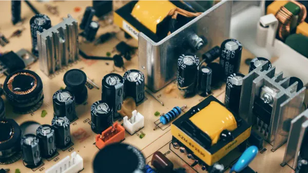
Electronic circuits, especially digital ones, need a clean and stable direct current (DC) power source. However, the power from a wall outlet is alternating current (AC). When you convert AC to DC, the resulting voltage is not perfectly smooth. It has small peaks and valleys called "ripple." This ripple is electrical noise that can cause circuits to malfunction.
A filter capacitor solves this problem. Placed after the rectifier in a power supply, the capacitor acts like a small, fast-recharging reservoir. It charges up during the voltage peaks and releases energy during the valleys. This action smooths out the ripple, providing a much cleaner DC voltage. The value on the capacitor symbol tells you how big this reservoir is. A larger microfarad value provides more filtering capability.
For common AC-to-DC power adapters, filter capacitors typically range from several microfarads to hundreds of microfarads. This capacity is necessary to smooth the rectified AC voltage effectively. In more advanced switch-mode power supplies (SMPS), you will find a bulk capacitor playing key roles at both the input and output.
| Location | Role of the Bulk Capacitor |
|---|---|
| Input | Stabilizes the input voltage and compensates for impedance from the power lines. |
| Output | Acts as a primary part of the output filter, reducing AC noise on the final DC voltage. |
Without the right capacitor, your power supply would deliver noisy power, making your electronic projects unstable or non-functional. The symbol on the capacitor is your guide to its filtering power.
Coupling and Decoupling Signals
In complex circuits like audio amplifiers or digital systems, you need to manage signals carefully. A capacitor allows you to pass certain signals while blocking others, a behavior dictated by its microfarad value. This leads to two distinct but related jobs: coupling and decoupling.
Coupling is the process of linking two different circuit stages together. An audio signal, for instance, is an AC signal that rides on top of a DC voltage. A coupling capacitor lets the AC audio signal pass through but blocks the DC voltage. This is crucial because the DC bias of one amplifier stage could interfere with the next.
- Connects two circuits, allowing AC to pass while blocking DC.
- Isolates the DC settings of each circuit stage.
- Prevents a DC load from interfering with an AC source.
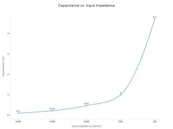
To choose the right coupling capacitor, you must match its value to the circuit's impedance and the frequencies you want to pass. The goal is to select a value that allows all desired frequencies through without distortion. As the chart below shows, a lower input impedance requires a larger capacitor to pass the same low frequencies.
| Input Impedance (Ohms) | Recommended µF Value |
|---|---|
| 500K | 0.1µF |
| 250K | 0.22µF |
| 100K | 0.47µF |
| 50K | 1µF |
| 10K | 4.7µF |
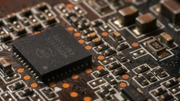
Decoupling, on the other hand, is used to protect circuits from noise. Digital integrated circuits (ICs) can generate high-frequency noise on the power supply line as they switch on and off rapidly. A decoupling capacitor, placed right next to the IC, shunts this unwanted noise to the ground, ensuring the IC has a clean power source. The 0.1µF capacitor is a hero in the digital world for this reason. This small capacitor is effective at filtering high-frequency noise, is compact, and is highly reliable. Each symbol on these tiny components plays a huge role.
Designing these complex systems requires deep expertise. For example, companies like Nova Technology Company (HK) Limited, a HiSilicon-designated (authorized) solutions partner, specialize in creating advanced electronic solutions where the precise selection of every component, right down to the capacitor symbol, is critical for performance and reliability.
Reading and Using Capacitor Markings
You must know how to read the markings on a capacitor to use it correctly. The capacitor symbol tells you its capacitance and other important details. Some components have clear labels, while others use a compact code. Learning to decipher each symbol is a key skill for any electronics builder.
Identifying Printed μF Values
Larger capacitors often make your job easy. They have their capacitance value printed directly on their casing. You can find these on big, cylindrical electrolytic capacitors.
- A large capacitor might clearly say '470µF 25V'. This symbol tells you the capacitance is 470 microfarads.
- Another common capacitor symbol is '100µF'.
- Sometimes, you will see a letter 'R' used as a decimal point. A capacitor with the symbol '4R7' has a capacitance of 4.7 µF.
Interpreting the Coded Capacitor Symbol
Smaller ceramic and film capacitors do not have enough space for printed values. They use a three-digit code as their capacitor symbol. This symbol is simple to understand once you learn the rule.
- First two digits: These are the first two numbers of the capacitance value.
- Third digit: This is the multiplier. It tells you how many zeros to add.
- The unit: The final number is always in picofarads (pF).
Let's decode the common '104' symbol. The first two digits are '10'. The third digit, '4', means you add four zeros. This gives you 100,000 pF. To convert this to microfarads, you divide by 1,000,000. So, a '104' capacitor has a capacitance of 0.1 µF. Similarly, a capacitor with the symbol '473' means 47 followed by three zeros, or 47,000 pF, which is 0.047 µF.
You might also see a letter after the number symbol, like '104K'. This letter indicates the tolerance of the capacitor. 'J' means ±5%, 'K' means ±10%, and 'M' means ±20%. This symbol tells you how much the actual capacitance might vary from the stated value.
Choosing the Right Capacitor for a Project
Selecting the right capacitor involves more than just reading a symbol. The required capacitance depends on the circuit's job. For a power supply filter, a larger capacitance provides smoother output voltage. However, in a timing circuit, the capacitance must be precise. A capacitor with too high a capacitance will slow down the charge and discharge rate, making your timing intervals longer than intended. If you find a capacitor with no markings, a multimeter with a capacitance setting is an essential tool to verify its value. Choosing the correct capacitor ensures your circuit behaves exactly as you designed it.
You now see the microfarad symbol is a blueprint for every capacitor. This important symbol dictates a capacitor's function, whether for timing, filtering, or signal management. The capacitance value is the primary specification. With over 3.9 trillion units shipped in 2023, understanding this symbol is vital. When troubleshooting, checking the capacitance value of a capacitor is a key step. The symbol gives you the target capacitance value. By mastering this symbol, you gain the power to predict, repair, and design circuits with confidence. The capacitance value symbol is your guide to a successful project.
FAQ
What is the difference between a capacitor symbol and a polarized capacitor symbol?
A standard capacitor symbol shows two parallel lines. This symbol indicates the capacitor can be connected either way. The polarized capacitor symbol uses a curved line or a plus symbol. This specific symbol means you must install the capacitor correctly. The polarized capacitor symbol is a critical instruction for every capacitor.
How do I find the capacitance value on a small capacitor?
You find the capacitance value using the three-digit symbol. This capacitor symbol is a code. The first two digits are the base capacitance value. The third digit tells you the number of zeros to add. This gives you the final capacitance value in picofarads for the capacitor.
Why does a capacitor have a voltage rating?
Every capacitor has a voltage rating. This symbol shows the maximum voltage the capacitor can handle safely. Exceeding this voltage can damage the capacitor. You must always choose a capacitor with a voltage rating higher than your circuit's voltage. This ensures the capacitor functions correctly and has a long life.
What does the capacitor symbol meaning tell me?
The capacitor symbol meaning provides key data. The main symbol is the capacitance symbol, which shows the capacitance value. Other parts of the capacitor symbol, like the polarized capacitor symbol, show polarity. The capacitance symbol and voltage symbol on a capacitor are essential for selecting the right capacitor.
Is a higher capacitance value always better for a capacitor?
No, a higher capacitance value is not always better. The correct capacitance value depends on the capacitor's job. A timing circuit needs a precise capacitance value. A larger capacitor stores more charge, but this can alter circuit timing. You must match the capacitance value to the design needs.