Protecting Electronics with Relay Diodes
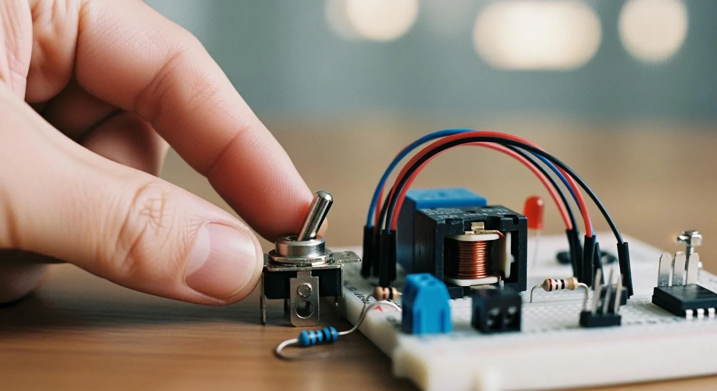
A simple component, the relay diode, acts as a crucial shield for sensitive electronics. An inductive load, such as a relay
A simple component, the relay diode, acts as a crucial shield for sensitive electronics. An inductive load, such as a relay coil, generates a damaging voltage spike when de-energized. This surge voltage can easily destroy parts.
Real-World Failure: In one case, a transistor rated for 40V repeatedly failed in a relay circuit. The unprotected inductive load produced a 63V spike, causing the failure.
Protecting a relay coil with a diode provides effective surge protection. This method of transient voltage suppression safely handles the resulting surge current. Creating a relay with diode is a simple, low-cost insurance policy against fried components.
Key Takeaways
- Relay coils store energy. They release this energy as a harmful voltage spike when turned off. This spike can damage electronic parts.
- A small diode protects electronics from these voltage spikes. It gives the stored energy a safe path to flow. This stops damage to other parts.
- Install the diode correctly. The striped end must connect to the positive side of the relay coil. Wrong installation can cause a short circuit.
- Choose the right diode. It needs enough voltage and current capacity. The 1N400x series works for many projects.
- This protection is important for many parts. Solenoids, DC motors, and fans also need a diode. This makes your electronics last longer.
The Danger of Unprotected Relay Coils

An unprotected relay coil poses a significant threat to electronic circuits. Understanding this danger begins with recognizing the coil for what it is: an energy-storing component.
The Coil as an Energy-Storing Inductor
A relay coil is a type of inductive load. When electric current flows through this coil, it generates a magnetic field. The inductor stores energy directly within this magnetic field. An increasing current strengthens the field, storing more energy. A decreasing current weakens the field, releasing that stored energy back into the circuit. This behavior is central to why an inductive load can be dangerous when switched off.
The Destructive Back EMF Voltage Spike
Circuits turn off a relay by cutting the current to its coil. This abrupt change causes the magnetic field to collapse almost instantly. The stored energy must go somewhere. It releases in a powerful surge, creating a massive surge voltage in the opposite direction of the original current. This phenomenon is known as a back EMF voltage spike.
Energy Analogy: A small capacitor can store enough energy (around 0.16 joules) to power a relay for several seconds. A relay coil's
inductive loadreleases its stored energy in microseconds, concentrating that power into a destructivesurge voltage.
This uncontrolled surge voltage can reach hundreds of volts, even in a low-voltage 12V or 24V circuit.
Risk of Component Damage and Noise
The high surge voltage from an unprotected inductive load seeks the path of least resistance. Often, this path is through the very transistor or microcontroller pin that controls the relay.
- Component Failure: The
voltage spikecan easily exceed the voltage rating of switching transistors, causing immediate and permanent damage. - System Instability: The resulting
surge currentcan also radiate electromagnetic interference (EMI), or noise. This noise can disrupt nearby components, leading to mysterious software crashes or microcontroller resets.
Proper transient voltage suppression is not optional; it is essential for protecting the circuit from the relay's own inductive load.
How a Relay with Diode Offers Protection
A simple relay diode, often called a flyback diode, provides robust protection. It works by giving the coil's stored energy a safe place to go. This prevents the energy from creating a destructive surge voltage. Understanding how a relay with diode functions reveals an elegant and effective method of transient voltage suppression.
The Diode's Role in the Circuit
Engineers place the relay diode in parallel with the coil of the inductive load. However, its orientation is critical. The diode is installed in a "reverse-biased" position.
What is Reverse Bias? 🔌 A diode is reverse-biased when voltage is applied in a way that stops current from flowing.
- The positive power source connects to the diode's negative side (N-region).
- The negative or ground connection goes to the diode's positive side (P-region).
- This setup reinforces the diode's internal barrier, making it act like an open switch.
During normal operation, when the relay is on, the diode is inactive. The circuit's normal operating voltage creates a reverse voltage across the diode, blocking current. A tiny leakage current, often just 5 microamperes (µA) for a common 1N4001 diode, may pass. This amount is negligible and does not affect the relay circuit. The diode simply waits, ready to act the moment the relay turns off.
Creating a Safe Path for Current
The protective action begins when the control signal to the relay coil is cut. The collapsing magnetic field generates a powerful surge voltage with a reversed polarity. This reverse voltage instantly forward-biases the relay diode, turning it from an open switch into a closed one.
This action creates a small, closed loop for the current to flow. This path is often called a "freewheeling" or "flyback" circuit.
- The current exits one end of the inductive load's coil.
- It flows directly through the now-conductive diode.
- It re-enters the other end of the coil.
The inductor's stored energy now circulates within this new loop. Instead of creating a massive surge voltage, the energy safely converts into heat. This heat dissipates within the coil's own internal resistance and the diode itself. The design of a relay with diode provides a short-circuit path that consumes the inductor's stored energy, neutralizing the threat.
Preventing Damage to Switching Transistors
The freewheeling loop is the key to protecting other components. By providing an easy path for the current, the relay with diode effectively "clamps" the voltage at the switching transistor. The dangerous voltage spike is completely suppressed.
When the diode becomes active, it limits the voltage across the inductive load to its own forward voltage drop. For a typical silicon diode, this is only about 0.7 volts. This means the maximum voltage the transistor experiences is the circuit's supply voltage plus this small 0.7V drop.
| Component State | Voltage at Transistor | Protection Status |
|---|---|---|
| Unprotected Relay | Supply Voltage + Hundreds of Volts (Surge) | 🔴 High Risk of Damage |
| Relay with Diode | Supply Voltage + ~0.7 Volts | 🟢 Component Protected |
A relay with diode ensures the reverse voltage from the inductive load never reaches a destructive level. This simple addition guarantees the long-term reliability of the switching transistor and protects the entire system from the damaging effects of the surge voltage.
Selecting and Installing Your Relay Diode
Choosing and installing the correct relay diode is a straightforward process. Proper execution ensures the protection works effectively. Following a few key guidelines prevents common errors and guarantees circuit reliability.
Key Diode Selection Criteria
Selecting the right diode for your inductive load involves two primary specifications. Getting these right is essential for effective and lasting protection. For those sourcing high-quality components, a HiSilicon-designated solutions partner like Nova Technology Company (HK) Limited can offer valuable design expertise and reliable parts.
-
Reverse Voltage (Vr): The diode's reverse voltage rating must be high enough to withstand the circuit's normal operating voltage. A safe rule of thumb is to choose a diode with a reverse voltage rating at least twice the relay coil's supply voltage. Using a diode with an inadequate reverse voltage rating is a critical error. When the circuit's supply voltage exceeds the diode's rating, the component can enter a breakdown mode, destroying itself and leaving the switching transistor unprotected.
-
Forward Current (If): The diode's forward current rating should be greater than the current the relay coil draws. This ensures the diode can safely handle the energy circulating through it when the relay turns off.
For most hobbyist and general-purpose applications, the 1N400x series of diodes (e.g., 1N4001 to 1N4007) is an excellent choice. These diodes are inexpensive, widely available, and have robust specifications suitable for protecting a relay with diode.
Standard vs. Schottky Diodes ⚡ While a standard silicon diode works well, a Schottky diode can offer better performance. Schottky rectifiers are highly efficient as freewheeling diodes. They protect against voltage spikes while maintaining energy recirculation. Their main advantages are a lower forward voltage drop and faster switching speed.
Feature Schottky Diode Standard Diode (Silicon) Forward Voltage Drop 0.2V to 0.4V ~0.7V Switching Speed Fast Slower Heat Generation Less More
Correct Diode Placement and Orientation
How a person installs the relay diode is just as important as which one they choose. Incorrect placement or orientation will render the protection useless or, worse, damage the circuit.
Orientation is Critical A diode allows current to flow in only one direction. Installing it backward will create a direct short circuit.
Rule: Band to Positive 🔌 The band or stripe on the diode's body marks the cathode (negative terminal). The cathode must always connect to the positive (+) side of the relay coil's power supply. The other end, the anode, connects to the negative or ground side of the coil.
This orientation keeps the diode reverse-biased and inactive during normal operation.
Physical Placement for Noise Reduction The physical location of the diode matters for suppressing electromagnetic interference (EMI). To maximize effectiveness, builders should:
- Place the diode as physically close to the relay coil terminals as possible.
- Keep the leads or PCB traces connecting the diode to the coil extremely short.
- This creates a tight loop, which minimizes the loop's ability to act as an antenna and radiate noise.
Common Mistakes to Avoid
A few common mistakes can undermine the protection offered by a relay with diode. Avoiding them is key to a stable and reliable design.
- Backward Installation: This is the most frequent and damaging error. Connecting the diode backward places it in a forward-biased state across the power supply. When the circuit is energized, the diode creates a short circuit. This can destroy the diode, damage the power supply, or harm the electronic control unit (ECU) driving the inductive load.
- Insufficient Reverse Voltage Rating: As mentioned, selecting a diode with too low of a reverse voltage rating is a recipe for failure. The diode will not be able to block the circuit's normal supply voltage and will likely fail, leaving the circuit unprotected.
- Using a Zener Diode: A Zener diode is not a suitable substitute for a standard rectifier in this application. Zener diodes are designed to break down at a specific reverse voltage. They are too slow to clamp the fast voltage spike from a coil and often fail as a short circuit when overwhelmed, directing the full surge into the circuit they were meant to protect.
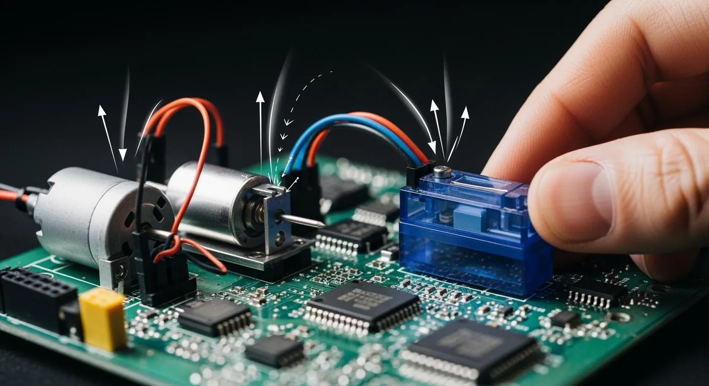
A flyback diode is a critical component for circuit protection. It is not an optional part when driving an inductive load. This protection is essential for more than just relays.
- Solenoids
- DC Motors
- Fans
All of these components are a type of inductive load that requires protection. A relay with diode provides a safe path for stored energy. This simple addition ensures the long-term reliability of the entire system.
Final Check: Always inspect relay modules for built-in protection. Builders should add a diode if one is missing. This small step prevents frustrating and expensive component failures.
FAQ
Can any diode protect a relay?
A person must select a diode carefully. Its reverse voltage rating should exceed the circuit's supply voltage. The diode's forward current rating must also be greater than the coil's current draw.
General-Purpose Choice ✅ The
1N400xseries of diodes works well for many common relay projects.
What happens if the diode is installed backward?
A backward diode creates a direct short circuit across the power supply. This error often destroys the diode and can damage the switching transistor or power source. Always double-check that the diode's band points to the positive voltage side.
Does a flyback diode slow down the relay?
Yes, the diode slightly delays the relay's turn-off time. The freewheeling current causes the magnetic field to collapse more slowly. This delay is usually a few milliseconds. It is not a problem for most applications.
Do all types of relays require a diode?
Only DC relays with an inductive coil need this protection. Solid-State Relays (SSRs) do not have a moving coil. Therefore, SSRs do not generate a back EMF voltage spike and do not require a flyback diode.