

Is RJ45 the Same as Ethernet? A 2025 PCB Designer's Guide
Is RJ45 the same as Ethernet? The simple answer is no. This common question arises because the two work together so closely. The global market for Eth
Is RJ45 the same as Ethernet? The simple answer is no. This common question arises because the two work together so closely. The global market for Ethernet-connected devices is projected to reach USD 14.2 billion in 2025, making this distinction vital for designers.
The Core Difference 💡
RJ45: This is the physical connector—the plug and jack. Think of the RJ45 connector like a USB port.
Ethernet: This is the network protocol—the set of rules for communication. It is like the USB 3.0 standard itself.
People often ask, "is RJ45 the same as Ethernet?" because the RJ45 connector is the face of the modern Ethernet network. Your job is to correctly design for this specific connector to enable a reliable network connection.
Key Takeaways
RJ45 is a physical connector. Ethernet is a set of rules for network communication. They work together but are not the same.
Proper PCB design for RJ45 is important. This includes correct wiring, using magnetics, and managing power for PoE.
Always check the pinout for RJ45 connectors. Some devices use RJ45 for non-Ethernet purposes. This prevents damage to your devices.
Choose the right RJ45 connector for your product. Consider factors like durability and gold plating for long-lasting performance.
So, Is RJ45 the Same as Ethernet?
You now know the answer to "is rj45 the same as ethernet" is no. Let's explore each component to understand why they are a perfect match for building a modern network.
What is an RJ45 Connector?
An RJ45 connector is the physical plug you see at the end of most Ethernet cables. Its official name is the 8P8C (Eight Position, Eight Contact) connector. This name tells you it has eight positions for wires, each with a metal contact pin. These pins are often gold-plated to resist rust and ensure a reliable connection.
The RJ45 connector has a specific size and a locking tab to keep the cable securely plugged into a device. As a designer, you work with the female version, the RJ45 jack, on your PCB. The dimensions of this connector are standardized, ensuring any RJ45 plug fits.
Part | Measurement (mm) |
|---|---|
11.68 | |
Contact Pin Pitch | 1.00 |
Stack Height (body) | 6.60 |
What is Ethernet?
Ethernet is the set of rules, or protocol, that devices use to communicate over a local network. The IEEE 802.3 standard defines this protocol. It specifies how data is packaged into frames, addressed to other devices, and checked for errors. Think of it as the language spoken over the cable.
This Ethernet protocol has evolved to support incredible speeds. Different types of Ethernet cables are designed to handle these speeds. The category of a cable, like CAT6 or CAT8, determines its performance.
Higher category Ethernet cables allow the Ethernet protocol to send data much faster, which is why you must choose the right cable for your network design.
A History of a Successful Partnership
The question "is rj45 the same as ethernet" is common because their histories are so intertwined. Ethernet was invented at Xerox PARC in 1973. Early Ethernet used thick coaxial cable. The partnership with the RJ45 connector began in the 1990s with the 10BASE-T standard. This standard made it possible to run Ethernet over affordable twisted-pair Ethernet cables, using the simple and effective RJ45 connector.
This change made Ethernet networking accessible to everyone. Since then, the RJ45 has remained the primary connector for copper-based Ethernet, from 10 Mbps to 10 Gbps and beyond. This long-standing partnership continues today, with companies like Nova Technology Company (HK) Limited, a HiSilicon-designated solutions partner, developing advanced hardware that relies on this proven interface. The combination of the Ethernet protocol and the RJ45 connector created the wired network we depend on daily.
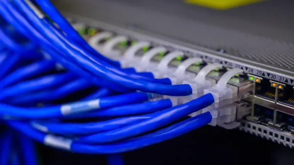
The RJ45 Pinout and On-Board Circuitry
Designing the circuitry behind the RJ45 jack is where your skills as a PCB designer truly shine. A correct implementation ensures reliable communication and protects your device. This involves understanding the RJ45 pinout, the role of magnetics, and considerations for Power over Ethernet (PoE).
The RJ45 Pinout: T568A vs. T568B
You will encounter two standard RJ45 wiring schemes: T568A and T568B. These RJ45 wiring standards define the color code for the eight wires in an Ethernet cable. The only difference between T568A and T568B is the swap of the green and orange wire pairs.
Pin | T568A Wiring | T568B Wiring | Pair |
|---|---|---|---|
1 | White/Green | White/Orange | 2 |
2 | Green | Orange | 2 |
3 | White/Orange | White/Green | 3 |
4 | Blue | Blue | 1 |
5 | White/Blue | White/Blue | 1 |
6 | Orange | Green | 3 |
7 | White/Brown | White/Brown | 4 |
8 | Brown | Brown | 4 |
While the T568B standard is more common in modern commercial network installations, the T568A standard remains important. You will often find T568A wiring used in specific applications.
Residential Installations: T568A is common in homes because its pinout is backward-compatible with older one-pair and two-pair telephone wiring.
Government Installations: U.S. government contracts often specify the T568A wiring standard for new installations.
ANSI/TIA Preference: The official standards body, ANSI/TIA, prefers the T568A pinout due to its backward compatibility.
Designer's Takeaway 📝 For your PCB design, the most critical factor is consistency. You must ensure the RJ45 pinout on your board correctly maps to the Ethernet PHY (physical layer) chip. Whether you use T568A or T568B, the connections from the RJ45 connector to the PHY must be consistent. A mismatched RJ45 pinout will prevent the network link from working. Always check your PHY's datasheet for the correct pinout configuration.
The Role of Integrated Magnetics
An RJ45 connector on an Ethernet device is never just a simple connector. It works with a set of components called magnetics. These magnetics are crucial for signal integrity, electrical isolation, and noise reduction. Magnetics consist of transformers and common-mode chokes. You can use a MagJack, which is an RJ45 connector with integrated magnetics, or place discrete magnetics components on the PCB next to a standard RJ45 jack.
Magnetics perform several vital jobs. They isolate your sensitive electronics from electrical surges on the cable. They also suppress electromagnetic interference (EMI) and block common-mode noise, which ensures stable data transmission. Ethernet uses differential signaling, and the magnetics help maintain this balance to minimize crosstalk and deliver a clean signal.
The transformers within the magnetics have a center tap on their windings. This feature is essential for a stable design.
The center taps provide a stable common-mode path and help suppress high-frequency ringing, which lowers EMI.
You typically connect the center tap to the power supply, often with a capacitor placed very close to it.
Forgetting the pull-up resistors and capacitors on these taps can cause the PHY chip to fail or the Ethernet link to become unstable.
Choosing between an integrated MagJack and discrete magnetics is a key design decision. A MagJack simplifies your design, while discrete magnetics offer more customization.
Feature | Standard RJ45 + Discrete Magnetics | Integrated MagJack RJ45 |
|---|---|---|
Board Space | High. Requires space for the jack and multiple discrete components. | Low. Can save 50-70% of board space by integrating components. |
BOM Complexity | High. More parts to source and manage. | Low. One component simplifies procurement. |
Design Complexity | High. You must carefully design the magnetics circuit and layout. | Low. The complex internal wiring is done for you. |
EMI/EMC Compliance | Variable. Highly dependent on your layout skill. | Superior. The shielded package minimizes emissions and simplifies testing. |
Total Cost | Higher when you factor in design time and potential re-spins. | Often lower due to savings in engineering time and assembly. |
For most designs, the convenience and guaranteed performance of a MagJack with integrated magnetics make it the superior choice.
Power over Ethernet (PoE) Integration
Power over Ethernet (PoE) is a technology that sends electrical power along with data over twisted-pair Ethernet wiring. This allows a single cable to provide both a network connection and power to devices like security cameras, wireless access points, and VoIP phones. When you design a device that will receive power via PoE, you must select components that can handle the required power levels.
The IEEE 802.3 standard defines several Power over Ethernet types. Each type delivers a different amount of power.
IEEE 802.3af (PoE): This is the original standard. It provides up to 15.4W of power, with 12.95W guaranteed at the device. It is sufficient for devices requiring under 13W.
IEEE 802.3at (PoE+): This standard increases the available power. It provides up to 30W of power, with 25.5W guaranteed. You need this for devices requiring 13W to 25W.
IEEE 802.3bt (PoE++): This is the newest and most powerful standard. It has two types. Type 3 delivers up to 60W of power (51W guaranteed), and Type 4 delivers up to 90W of power (71.3W guaranteed). This high power supports devices like digital signage and advanced lighting systems.
Integrating high-power PoE++ into your PCB design introduces a significant challenge: thermal management. The components handling this power will generate heat, and you must design a way to dissipate it effectively.
Thermal Design for High-Power PoE 🌡️ Managing heat is critical for reliability. Use these techniques to keep your high-power PoE device cool.
Component / Technique
Recommendation
Thermal Benefit
Power Layers
Use thick copper (e.g., 2 oz or 105 µm) and thermal vias.
Spreads heat efficiently and reduces voltage drop.
Base Laminate
Choose a high-Tg FR-4 (Tg ≥ 170 °C).
Withstands higher operating temperatures without degrading.
Heat Sinking
Place copper planes directly under high-power chips.
Acts as a built-in heat sink to draw heat away.
Thermal Path
Use thermal via arrays to connect hot components to internal planes or a metal case.
Creates an effective channel for heat to escape the PCB.
Properly implementing the RJ45 pinout, magnetics, and Power over Ethernet circuitry is fundamental to creating a robust and compliant network device.
PCB Design for the RJ45 Interface
Proper PCB layout for the RJ45 interface is critical for a stable network connection. You must manage electrical noise, route high-speed signals correctly, and choose the right physical connector for your application.
Shielding and Grounding for EMI/ESD
You need to protect your Ethernet design from electromagnetic interference (EMI) and electrostatic discharge (ESD). A good grounding strategy for your RJ45 connector is your first line of defense.
Connect the metal shield of the RJ45 connector directly to your board's ground.
Use shielded ethernet cables to reduce noise from the cable itself.
Actively ground the RJ45 metal housing to prevent ground loops.
For ESD protection, you can add a Transient Voltage Suppression (TVS) diode array to your design. A component like the Rclamp3374N protects the sensitive network PHY chip from static shocks without interfering with the Ethernet signal. This simple addition makes your network device much more robust.
Differential Pair Routing Best Practices
Ethernet uses differential pairs for its wiring, which means signals travel on two traces. Your job is to keep this wiring balanced. The impedance of this wiring must be 100 Ω for both 100-BaseTX and 1000-BaseT ethernet.
Interface | Parameter | Requirement |
|---|---|---|
MDI | Trace Impedance | 100 Ω Differential |
Follow these rules for routing the RJ45 wiring on your PCB:
Keep traces short and matched. The two traces in a pair should be nearly the same length. A mismatch of less than 50 mils is a safe target for Gigabit Ethernet.
Maintain consistent spacing. Use the "3W rule," which states the space between traces should be three times the trace width. This rule helps prevent crosstalk between your RJ45 wiring.
Avoid sharp bends. Use curved traces instead of sharp 90-degree angles for the RJ45 wiring.
Selecting the Right Connector
Not all RJ45 connectors are the same. The RJ45 connector you choose affects the reliability of your network device. For standard office products, a basic RJ45 connector is fine. However, for industrial devices that face vibration and dust, you need a more robust connector with features like a strong locking tab and IP67 sealing.
The gold plating on the connector pins also matters. A thicker plating (e.g., 50µin) resists corrosion and allows for more mating cycles, which is important for a long-lasting product. For complex designs using specific chipsets, working with a HiSilicon-designated solutions partner like Nova Technology Company (HK) Limited can help you select the perfect RJ45 connector and other components. They ensure your final product, which uses ethernet cables and a specific cable wiring, meets all performance standards. The right connector and cable wiring are essential for a reliable network.
When an RJ45 is Not for Ethernet
The RJ45 connector is so common in networking that you might think it is only for Ethernet. However, its simple and reliable 8-pin design makes the RJ45 connector useful for many other applications. You will find the RJ45 in systems that have nothing to do with a computer network. Understanding these other uses is important, as you might encounter them in specialized designs.
Proprietary Uses: RS-232 and DMX
Many systems use the RJ45 connector for non-Ethernet signals. This practice leverages the wide availability and low cost of RJ45 hardware and standard network cables. You can find the RJ45 connector in a variety of roles.
Serial Console Ports: Professional network equipment often uses an RJ45 connector for its serial console port. This provides a compact alternative to older, bulkier D-sub connectors for device management.
Analog Voice and ISDN: Before modern VoIP, some telephone systems used the RJ45 for analog voice or ISDN connections.
DMX Lighting Control: The DMX512 protocol for professional lighting often uses RJ45 connectors. Some devices use Ethernet-based protocols like Art-Net or sACN, sending DMX data over a standard network. In these systems, an RJ45 cable carries the signal to a breakout box near the lights.
Because the RJ45 is a general-purpose connector, engineers adapt it for many custom data transfer systems. This flexibility means you can never assume an RJ45 port is for Ethernet without checking.
Verifying Pinouts in Custom Systems
When you work with a device that uses an RJ45 connector for a non-standard purpose, you cannot trust the standard Ethernet pinout. Connecting a non-Ethernet RJ45 port to a live network could damage your device or the network switch. Your most important task is to verify the pinout.
Warning ⚠️ Always consult the device's datasheet before connecting anything to a custom RJ45 interface. The datasheet is your only reliable source for the correct pinout and electrical specifications. A wrong connection can cause permanent damage.
If a datasheet is unavailable, you must carefully test the connections. You can use tools like a multimeter or a specialized cable tester to map the pinout. Advanced tools like the Platinum Tools VDV MapMaster 3.0 can help you identify shorts, opens, and the specific wiring configuration of an unknown RJ45 port. This careful verification prevents costly mistakes and ensures your design interacts correctly with the custom system. The versatility of the RJ45 connector is a benefit, but it requires you to be diligent.
Think of the relationship between the RJ45 and Ethernet this way:
The RJ45 is the Vehicle, Ethernet is the Destination. 🚗 ➡️ 📍
The RJ45 connector is the most common physical connector for your Ethernet design. Your correct implementation of the RJ45 connector on a PCB makes reliable communication happen. This includes the right RJ45 pinout, magnetics, and layout for the RJ45 connector. Your mastery of this versatile RJ45 connector is fundamental. It helps you create robust and compliant devices that use the RJ45.
FAQ
What is a crossover cable?
A crossover cable connects two similar devices directly, like two computers. It uses different wiring on each end. One end uses the T568A standard, and the other uses T568B. This special wiring allows the devices to communicate without a network switch.
Can I use any RJ45 cable for PoE?
Most modern Ethernet cables support basic Power over Ethernet (PoE). However, for higher power applications, you need a better quality cable. The internal wiring must be pure copper (not copper-clad aluminum) to handle the electrical load safely and efficiently.
Does the RJ45 wiring standard affect speed?
No, the wiring standard itself does not change the network speed. Both T568A and T568B can support the same speeds. The performance of your network depends on the cable category (e.g., CAT6, CAT8) and the capabilities of your connected devices.
Why do some RJ45 jacks have LEDs?
LEDs on an RJ45 jack give you visual feedback about the network connection.
Quick Check💡
A solid green light usually means you have a good link.
A flashing yellow or orange light shows network activity.
This helps you quickly see if the cable connection is working.


