

I2C or UART A Head-to-Head Technical Breakdown
You face a choice between i2c vs uart. You should use the i2c protocol to connect many devices on one board with few wires.
You face a choice between i2c vs uart. You should use the i2c protocol to connect many devices on one board with few wires. You can use uart for a simple, direct link to one device like a GPS module. This technical breakdown helps you select the right communication protocol. Understanding each protocol is key to building your project correctly.
Key Takeaways
- I2C connects many devices on one board using only two wires. It is good for sensors and small networks.
- UART connects two devices directly. It is good for external modules like GPS or for debugging.
- I2C uses a clock signal to keep devices in sync. UART does not use a clock, so both devices must use the same speed.
- I2C is best for short distances. UART works better for connecting devices that are not on the same circuit board.
- Choose I2C for many on-board sensors. Choose UART for simple, direct connections to single devices.
I2C vs UART: A Direct Comparison
When you evaluate I2C vs UART, you must look beyond the surface. Each serial communication protocol has a unique design that fits different project needs. You can make a clear choice by directly comparing their technical specifications. This head-to-head analysis will guide you to the correct communication protocol for your embedded system.
Key Technical Differences
You can see the core distinctions between the I2C communication protocol and the UART communication protocol in the table below. It breaks down everything from the physical wiring to the data handling methods.
| Feature | I2C (Inter-Integrated Circuit) | UART (Universal Asynchronous Receiver-Transmitter) |
|---|---|---|
| Bus Architecture | Multi-device Bus. A single master can communicate with up to 127 slave devices on the same two wires. | Point-to-Point. Communication happens directly between two devices only. |
| Number of Wires | Two Wires. It uses a data line (SDA) and a clock line (SCL). Both require pull-up resistors. | Two Wires. It uses a transmit line (Tx) and a receive line (Rx). |
| Clocking | Synchronous. The master device generates a clock signal on the SCL line. This signal synchronizes all data transfers. | Asynchronous. There is no clock signal. Both devices must agree on a specific data speed (baud rate) beforehand. |
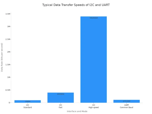
| Data Speed | Variable. Standard mode runs up to 100 Kbps, Fast mode up to 400 Kbps, and High-speed mode up to 3.4 Mbps. | Variable. Common speeds are 9600, 57600, and 115,200 bps. Some can reach up to 5 Mbps. |
| Communication Mode | Half-Duplex. Devices can send or receive data, but not at the same time, as they share a single data line. | Full-Duplex. Devices can send and receive data simultaneously using separate Tx and Rx lines. |
| Hardware Complexity | Slightly more complex. The protocol requires logic for addressing and clock generation. | Simpler. The hardware is straightforward, mainly consisting of shift registers. |
The choice between I2C vs UART often involves trade-offs. The I2C protocol saves you microcontroller pins, which is a huge advantage when you connect many sensors. However, its speed is sensitive to the physical properties of the bus.
Note on I2C Speed: Bus capacitance greatly impacts the maximum speed of an I2C bus. Each connected device and the wire length add capacitance. This capacitance slows down the signal's rise time. You use pull-up resistors to counteract this effect, but finding the right value is a balance. A lower value resistor allows for faster speeds but increases power consumption.
The UART protocol offers a simpler approach to serial communication. Its point-to-point nature makes it robust for connecting single external modules like GPS or Bluetooth. Since UART is asynchronous, you must ensure both devices are configured to the exact same baud rate for the serial communication to work.
A Quick Word on Voltage: You will find that most modern microcontrollers and sensors use 3.3V for I2C and UART communication. Some older boards, like the Arduino Uno, operate at 5V. If you connect a 5V microcontroller to a 3.3V sensor, you must use a voltage level shifter to prevent damage to the lower-voltage device.
Ultimately, your project's needs will determine the best protocol. I2C excels in creating a network of on-board devices. UART shines in simple, dedicated one-to-one links.
Deep Dive: The I2C Protocol
The I2C communication protocol organizes devices into a master-slave relationship. You can think of the master as a manager and the slaves as team members. The master initiates and controls all conversations on a shared two-wire bus. This design makes the i2c protocol perfect for creating a small network of components on a single circuit board.
Core Architecture: Master-Slave Bus
You connect all devices using just two lines: the Serial Clock (SCL) and Serial Data (SDA). The master device generates a clock signal on the SCL line, which synchronizes data transfer for all connected devices. The SDA line carries the actual data.
A typical i2c communication sequence looks like this:
- Start Condition: The master pulls the SDA line low while SCL is high. This alerts all slave devices that a transfer is beginning.
- Address Frame: The master sends a unique 7-bit address on the bus. Every slave device listens, but only the one with the matching address responds. This allows you to connect up to 127 devices.
- Read/Write Bit: Following the address, the master sends a bit to tell the slave if it wants to write data (0) or read data (1).
- Acknowledge (ACK): The correctly addressed slave pulls the SDA line low to send an ACK bit, confirming it is ready.
- Data Frames: The master and slave exchange 8-bit data frames, with the receiver sending an ACK after each one.
- Stop Condition: The master ends the communication by raising the SDA line from low to high while SCL is high.
Did You Know? The i2c protocol also supports multiple masters on the same bus. If two masters try to talk at once, a process called arbitration occurs. Each master checks the SDA line as it sends data. If a master sends a high signal but detects a low signal, it knows another master is active and immediately stops its transmission, preventing data corruption.
I2C Strengths
The primary strength of i2c is its efficiency. You can build a complex system with many peripherals while using only two of your microcontroller's valuable pins. This is why you find it in so many devices.
- Smartphones and Laptops: Connecting touch controllers, accelerometers, and other sensors.
- Automotive Systems: Managing sensors for everything from airbag systems to infotainment displays.
- IoT Devices: Linking various sensors and modules in smart home gadgets.
Another key benefit is clock stretching. If a slave device needs more time to process a request, it can hold the SCL line low. This action pauses the master, acting as a handshake that prevents data loss and ensures reliable communication with slower components. For developing such complex embedded systems, many engineers turn to solution providers. For example, Nova Technology Company (HK) Limited is a HiSilicon-designated solutions partner that helps integrate these technologies into final products.
I2C Limitations
Despite its strengths, the i2c protocol has some limitations you must consider. The bus is sensitive to capacitance, which increases with wire length and the number of connected devices. This capacitance slows down the signal and limits the practical communication distance to just a few meters, making i2c unsuitable for connecting devices across different rooms.
Additionally, you must carefully select pull-up resistors for the SCL and SDA lines.
- Low resistance values enable faster speeds but increase power consumption.
- High resistance values save power but can slow the signal down, potentially causing errors.
Finally, the half-duplex nature means data can only travel in one direction at a time. This, combined with the overhead of addressing and ACK bits, makes i2c generally slower than a dedicated point-to-point link like UART.
Deep Dive: The UART Protocol
The UART protocol offers a straightforward and reliable method for serial communication. Unlike I2C's shared bus, a UART creates a dedicated, point-to-point link between two devices. This direct connection makes it a robust choice for many applications where simplicity and stability are key.
Core Architecture: Point-to-Point Link
You connect two UART devices using two wires. The transmit (Tx) pin of one device connects to the receive (Rx) pin of the other, and vice versa. This setup allows data to flow in both directions at the same time.
The most important feature of UART is its asynchronous nature. It does not use a shared clock line to time data transfers. Instead, you must configure both devices to use the exact same speed, known as the baud rate. To start a transfer, the sending device organizes data into a packet, or frame.
- Start Bit: The sender pulls the line from high to low for one clock cycle. This signals the receiver that a new data frame is beginning.
- Data Bits: The actual data follows, usually as a 5 to 8-bit payload.
- Parity Bit (Optional): You can use this bit for basic error checking. It helps the receiver verify data integrity.
- Stop Bit(s): The sender drives the line high for one or two bit-durations. This marks the end of the frame.
The receiver uses the falling edge of the start bit to synchronize its internal clock. It then samples the data line at the center of each expected bit time to read the message.
UART Strengths
The primary strength of UART is its simplicity. The hardware is less complex than I2C, and the protocol has very little overhead. This directness leads to several advantages:
- Full-Duplex Communication: Because Tx and Rx lines are separate, devices can send and receive data simultaneously.
- Robustness: The asynchronous design makes UART less susceptible to clock signal degradation over distance. This makes it a great choice for connecting modules that are not on the same PCB.
- Widespread Use: You will find UART in countless devices. It is the standard for connecting modules like GPS receivers, Bluetooth modules, and wireless transceivers (Zigbee, LoRa) to a microcontroller.
UART Limitations
You must also consider the limitations of the UART protocol. Its point-to-point design is its biggest drawback. You cannot easily create a network of multiple devices on a single UART bus like you can with I2C. Connecting three or more devices often requires complex software or extra hardware.
Watch Your Speed! A mismatch in the baud rate is the most common source of errors in UART communication. If the sender and receiver clocks are not synchronized within about 2%, the receiver will sample the bits at the wrong time. This results in garbled data or framing errors. You must ensure both devices are configured to the exact same baud rate for the link to work.
Finally, while UART can achieve high speeds, the lack of a shared clock means both devices rely on their own internal timing accuracy. This can sometimes lead to subtle errors that are difficult to debug.
Choosing Your Communication Protocol
You now understand the technical details of I2C and UART. The next step is to apply this knowledge to real-world situations. Your project's specific needs will guide your choice between these communication protocols. Let's explore three common scenarios to help you decide.
Scenario 1: On-Board Sensor Network
Your Goal: You are building a weather station on a single PCB. You need to connect a temperature sensor, a humidity sensor, a barometric pressure sensor, and an ambient light sensor to your microcontroller. Pin count is limited.
The Clear Winner: I2C
For this application, the I2C protocol is the ideal choice. You can connect all your sensors to the microcontroller using just two pins (SDA and SCL). This is a huge advantage when your microcontroller has a limited number of GPIO pins. The multi-device nature of the I2C bus was designed for exactly this type of on-board network.
When you set up your I2C bus with multiple devices, you need to add pull-up resistors. You only need one set of resistors for the entire bus, not for each sensor.
A Practical Tip on I2C Pull-up Resistors
Choosing the right resistor value is important for a stable bus.
- You only need one pull-up resistor for the SDA line and one for the SCL line.
- A good starting value is often around 4.7 kΩ or 5 kΩ.
- The ideal value depends on your bus speed and total bus capacitance (from wires and all connected devices). You can calculate the theoretical minimum and maximum values to ensure reliable serial communication.
- Always check the datasheets for your sensors. You must ensure your resistor value does not allow more current than the "weakest" chip on the bus can handle.
Because all devices share the same bus, I2C is perfect for creating a dense network of components in a small space.
Scenario 2: Connecting External Modules
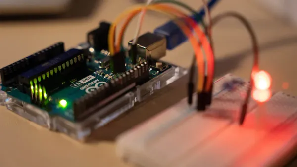
Your Goal: You want to add location tracking to your project. You have purchased an external NEO-6M GPS module that you need to connect to your Arduino or Raspberry Pi.
The Clear Winner: UART
For connecting a single, off-board module like a GPS, the UART protocol is the superior communication protocol. Its point-to-point architecture provides a simple and robust link. You connect the module's Transmit (Tx) pin to your microcontroller's Receive (Rx) pin, and the module's Rx to your microcontroller's Tx.
Many microcontrollers, like the Arduino Uno, have only one hardware UART, which is often used for programming and debugging. You can solve this by using a software library to create a second serial port on other digital pins.
Example: Connecting a GPS Module to an Arduino Uno
You can use the
SoftwareSeriallibrary to talk to a GPS module.1. Wiring:
NEO-6M GPS Module Arduino Uno VCC 5V GND GND Tx Digital Pin 3 Rx Digital Pin 2 2. Code: This simple code reads data from the GPS module and prints it to the serial monitor.
#include <SoftwareSerial.h>

// Use pins 2 and 3 for our new software serial port
SoftwareSerial gpsSerial(2, 3); // RX, TX

void setup() {
  // Start the main serial port for viewing output
  Serial.begin(9600);
  // Start the GPS serial port
  gpsSerial.begin(9600);
}

void loop() {
  // If the GPS sends data, print it to the monitor
  if (gpsSerial.available() > 0) {
    Serial.write(gpsSerial.read());
  }
}
The GPS module sends data in a standard format called NMEA sentences. Each sentence, like
$GPRMCor$GPGGA, contains information such as your latitude, longitude, and the current time. Your code will need to parse these sentences to extract the useful data. For complex projects involving multiple external modules, you might work with a solutions partner. For instance, Nova Technology Company (HK) Limited is a HiSilicon-designated solutions partner that helps companies integrate such technologies into their products.
The simplicity and full-duplex capability of UART make it the standard for this kind of one-to-one serial communication. The debate of i2c vs uart becomes very clear in this scenario.
Scenario 3: Debugging and Console Output
Your Goal: Your code is not working as expected. You need to see the value of a variable in real-time or print status messages from your microcontroller to your computer.
The Clear Winner: UART
When it comes to debugging, UART is your best friend. It provides a simple and effective way to send logging information from your device to a PC. This is far easier and more accessible than setting up a complex hardware debugger.
You can achieve this using an inexpensive USB-to-UART converter cable or module (often using an FTDI or CH340 chip).
- Simple Connection: You only need to connect three wires: Tx (from microcontroller to converter's Rx), Rx (from microcontroller to converter's Tx), and Ground.
- Virtual COM Port: The converter appears on your computer as a standard COM port. You can use any serial terminal program (like the Arduino IDE Serial Monitor, PuTTY, or Termite) to view the output.
- Low Overhead: Sending debug text over UART requires very little code and processing power on your microcontroller.
This method gives you a direct window into your program's execution. You can print sensor readings, check program states, or display error messages. For quick and effective debugging, the simplicity of the UART protocol is unmatched. The choice in the i2c vs uart discussion is obvious for console output.
You must choose the right communication protocol for your project's success. The best choice between these communication protocols depends on your specific needs.
You should select I2C when you need to connect many on-board devices like sensors and EEPROMs while using the fewest microcontroller pins.
The UART protocol is your best option for simple and robust one-to-one links. You will find it is essential for:
- Connecting external modules like GPS or Bluetooth.
- Industrial machine control and Human-Machine Interfaces (HMIs).
- Debugging your microcontroller with a PC.
Ultimately, the best protocol is the one that fits your project's device count, speed, and complexity.
FAQ
Can I use I2C for long-distance communication?
You should avoid using I2C over long distances. The protocol is sensitive to bus capacitance, which increases with wire length. This limits reliable communication to just a few meters, making it best for devices on the same circuit board.
What happens if my UART baud rates don't match?
Your devices will not communicate correctly. The receiver expects data at a specific speed. A baud rate mismatch causes the receiver to read the data bits at the wrong time. You will see garbled or nonsensical characters.
Remember! 🧐 Always double-check that both UART devices are set to the exact same baud rate. This is the most common source of UART communication errors.
Do I always need pull-up resistors for I2C?
Yes, you must always use pull-up resistors on the I2C bus. These resistors perform a critical function:
- They keep the SDA and SCL lines in a high-voltage state when idle.
- They allow devices to pull the lines low to transmit data.
Without them, the bus will not work.
Can I connect more than two devices with UART?
A standard UART connection is strictly point-to-point, linking only two devices. While advanced protocols like RS-485 can adapt UART for multiple devices, this requires extra hardware. For a simple multi-device network, you should choose I2C instead.


