

Circuit Performance Under Thermal Stress A TCR Study
A circuit can fail despite perfect design. Real-world temperature changes often degrade circuit performance. The primary cau
A circuit can fail despite perfect design. Real-world temperature changes often degrade circuit performance. The primary cause is the temperature coefficient of resistance (TCR). The resistor temperature coefficient, or TCR, dictates resistor performance. A high TCR is a problem, while a low TCR is ideal. The TCR is critical. Think of a bridge expanding in heat; a resistor's value changes similarly. Understanding the TCR is vital for high-accuracy electronic systems. Designers must mitigate temperature effects for a stable circuit. The TCR specification, or TCR, is the key. A low TCR is a good TCR.
Key Takeaways
- The Resistor Temperature Coefficient (TCR) shows how much a resistor's value changes with temperature. A low TCR is best for stable circuits.
- Temperature changes can make circuits less accurate. This is because resistors' values drift. This drift affects how the circuit works.
- Designers can choose special resistors with very low TCRs for precise circuits. They can also use design tricks like good PCB layouts to manage heat.
- Matched resistor pairs help keep circuits stable. They are made to change resistance together, which keeps their ratio steady.
- Understanding TCR helps prevent circuit failures. It is important for making reliable electronic devices.
Understanding the Resistor Temperature Coefficient
The resistor temperature coefficient, often symbolized as α (alpha), is a critical specification. It defines how much a resistor's value changes for each degree Celsius (°C) of temperature change. This value is typically expressed in parts per million per degree Celsius (ppm/°C). A TCR of 100 ppm/°C means the resistance will change by 0.01% for every 1°C shift. Understanding this metric is fundamental to improving resistor stability and overall circuit reliability.
The Source of Thermal Instability
Temperature changes cause physical effects within resistive materials, altering resistor performance. The specific effect depends on the material type.
- Conductors: In metals, rising temperatures cause atoms to vibrate more. This increased vibration leads to more collisions for the electrons moving through the material, which increases resistance.
- Semiconductors: In semiconductors, higher temperatures increase thermal agitation. This process creates more free charge carriers, which improves conductivity and causes resistance to decrease.
This inherent resistor temperature sensitivity is the root cause of thermal drift in a circuit.
Impact on Circuit Stability and Accuracy
Even a small TCR can significantly impact a circuit. Consider a simple voltage divider, a common building block in electronics. If the resistors in the divider have a non-zero TCR, their values will drift with temperature. This drift alters their ratio, causing the output voltage to become inaccurate.
Real-World Impact: In an operational amplifier circuit, gain accuracy depends on the ratio of external resistors. If these resistors have different TCR values, the amplifier's gain will shift with temperature. This effect is especially critical in high-precision applications like systems using A/D converters with more than 10-bit resolution. The temperature coefficient of resistance directly compromises resistor stability and precision.
Positive vs Negative TCR Explained
The TCR specification indicates both the magnitude and direction of resistance change.
- A Positive TCR means resistance increases as temperature rises. Most standard resistors exhibit a positive TCR.
- A Negative TCR means resistance decreases as temperature rises.
While a low TCR is often desired for stable resistor performance, some components are designed with a high negative TCR for specific functions. Negative Temperature Coefficient (NTC) thermistors are a prime example. Their predictable resistance drop with heat makes them ideal for temperature sensing and management in smartphones, medical devices, and automotive systems. Materials like carbon, cermet, and certain metal films can also be engineered to have a negative TCR.
The Temperature Coefficient of Resistance in Practice
Understanding the theory of the temperature coefficient of resistance is the first step. Applying this knowledge in practice requires selecting the right components and anticipating thermal challenges. An engineer's choice of resistor technology directly influences resistor performance and overall resistor stability.
Comparing Common Resistor Technologies
Different resistor types exhibit vastly different TCR values. The material and construction method determine the component's resistor temperature sensitivity. This variation allows designers to balance cost and performance.
| Resistor Type | Typical TCR Range (ppm/°C) |
|---|---|
| Carbon Film | ±200 to ±1500 |
| Metal Film | 20–200 |
| High Precision Film (Thin Film) | ±2 to ±25 |
For general-purpose applications, metal film resistors offer a good balance. However, demanding systems require high-precision resistors. Metal foil resistors, for instance, offer an exceptionally low TCR, with standard values around ±1 ppm/°C. Some specialized variants achieve a TCR as low as 0.05 ppm/°C. While these high-precision resistors carry a higher initial cost, their superior resistor stability justifies the investment in critical applications like metrology equipment, where long-term accuracy is paramount.
Sources of Thermal Stress in Electronics
Temperature changes in a circuit originate from two primary sources: external environment and internal self-heating.
- External (Ambient) Temperature: A device's operating environment dictates its baseline temperature. Electronics must function reliably across wide temperature ranges, such as commercial (0°C to 70°C) or industrial and automotive (-40°C to 85°C).
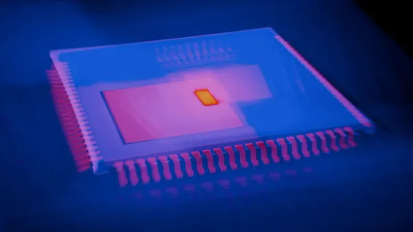
- Internal (Self-Heating): Current flowing through a resistor generates heat due to power dissipation (
P = I²R). This effect, known as self-heating, raises the component's temperature above the ambient level. Engineers can estimate this temperature rise by using the component's thermal resistance value, a specification found in datasheets. A higher power dissipation leads to a greater internal temperature increase, which in turn affects the resistor performance due to its TCR.
Leveraging High TCR in Compensation Circuits
While a low TCR is usually desirable for stable resistor performance, a high TCR can be a powerful design tool. Engineers can use a resistor with a predictable, high positive TCR to stabilize a circuit. Some circuit elements exhibit a negative temperature drift, meaning their output decreases as temperature rises.
Design Tip: A silicon-based resistor with a high positive TCR (up to +6000 ppm/°C) can be placed in the circuit to counteract this drift. As the temperature increases, its resistance rises, compensating for the other component's negative drift. This clever technique uses the resistor temperature coefficient to maintain a stable output across a range of temperatures, improving the reliability of the entire circuit.
Strategies for Thermal Stability
Achieving thermal stability requires more than just choosing a component with a low temperature coefficient of resistance. It demands a holistic approach that begins with component selection and extends through circuit layout and system-level design. Proactive strategies are essential for mitigating thermal drift and ensuring consistent resistor performance.
Reading Datasheets for Optimal Resistor Performance
A resistor datasheet is the primary source of truth for its thermal characteristics. Understanding how to interpret this document is a critical skill for any engineer. Manufacturers typically present the TCR in tables, which may show resistance values at different temperatures and the corresponding TCR.
For high-precision resistors, datasheets often provide more detailed information. It is common practice for manufacturers to define separate TCR specifications for different temperature ranges. This is because the resistance change is not always linear across the entire operating spectrum. You will often find:
- 'Cold' TCR: This specification defines the chord slope for the TCR from –55°C to +25°C.
- 'Hot' TCR: This specification applies to the chord slope from +25°C to +125°C.
These 'hot' and 'cold' TCR values give a more accurate picture of resistor performance under varying conditions. Some manufacturers of high-precision resistors, like those making Bulk Metal® Foil components, provide nominal TCR curves that cover a broad range, often from –55°C to +125°C. These datasheets specify the maximum spread for each TCR slope, giving designers a clear understanding of the component's worst-case drift. A thorough review of the datasheet ensures the selected component's TCR meets the circuit's stability requirements.
Design Techniques to Minimize Thermal Drift
Beyond component selection, several design techniques can minimize the impact of temperature on a circuit. These strategies focus on managing heat at the board level to maintain a stable operating environment for sensitive components.
PCB Layout Best Practices 📝 A well-planned PCB layout is a powerful tool for thermal management. The goal is to distribute heat evenly and keep critical components at a consistent temperature.
- Component Placement: Position high-power components, like voltage regulators, toward the center of the board to allow heat to dissipate in all directions. Place temperature-sensitive components, such as high-precision resistors or op-amps, in cooler areas and away from heat sources.
- Trace Routing: Use wider traces for high-current paths to reduce resistance and heat generation (
P = I²R). Route these traces away from thermally sensitive circuitry.- Heat Dissipation: Utilize large copper planes for ground and power. These planes act as effective heat sinks, increasing the surface area for heat dissipation and promoting a more uniform board temperature.
- Thermal Vias: Incorporate thermal vias directly under heat-generating components. These vias create a low-resistance path for heat to travel to other layers or to a heatsink on the opposite side of the board, improving overall thermal transfer.
For high-power applications, active cooling methods are often necessary. Heatsinks draw heat away from a component, while forced-air cooling with fans can dramatically increase the rate of heat transfer. For example, a power resistor might only handle 29 W in a 50°C ambient environment, but with forced-air cooling that keeps its heatsink at 25°C, it could handle its full rated power of 100 W. This demonstrates how active cooling directly improves resistor stability under load.
Using Matched Resistor Pairs for Tracking
In many precision circuits, such as differential amplifiers or voltage dividers, the ratio between two resistors is more important than their absolute values. In these cases, ensuring the resistors' TCR values track each other is paramount for resistor stability.
Kelvin Connections for Accuracy For high-current sense resistors, a four-wire Kelvin connection is essential. This technique uses two wires to apply current and two separate wires to measure voltage directly across the resistive element. This method eliminates the resistance and TCR of the PCB traces from the measurement, preventing them from introducing temperature-sensitive errors. This is crucial for maintaining accuracy, especially with low-ohm high-precision resistors.
The best way to achieve excellent TCR tracking is by using matched resistor pairs or integrated resistor networks. These components are fabricated from the same resistive material on a single substrate. This monolithic construction ensures several key advantages:
- Superior TCR Tracking: Because the resistors are made together, their TCR characteristics are nearly identical. As temperature changes, their resistance values drift up or down together, keeping their ratio extremely stable.
- Thermal Proximity: The resistors are physically close, so they experience the same temperature. This eliminates errors caused by thermal gradients across the PCB.
- Reduced Assembly Costs: Using a single component instead of multiple discrete ones simplifies the manufacturing process.
For applications demanding the highest precision, integrated resistor arrays offer unmatched resistor stability and TCR tracking, making them an ideal choice over discrete high-precision resistors.
Managing the TCR is critical for robust circuit performance. Smart component selection and design improve resistor stability. Understanding the TCR prevents costly failures, like the $34 million Anker recall caused by thermal instability. A low TCR improves resistor performance. The TCR is key. A good TCR ensures resistor stability. A low TCR is a good TCR.
Take Action! 💡 Engineers should immediately check the TCR for a critical resistor in their current circuit. The TCR specification, or TCR, is the key to better resistor performance.
FAQ
What is a "good" TCR value?
A "good" tcr value depends on the application. General-purpose circuits may tolerate values around 100 ppm/°C. High-precision systems, like medical or metrology equipment, often require a very low tcr, typically below 10 ppm/°C, to ensure maximum stability and accuracy.
Does self-heating always affect circuit performance?
Yes, self-heating always raises a component's temperature above the ambient level. This temperature increase causes resistance to drift. In high-power or high-precision circuits, this effect can significantly degrade performance. Designers must account for it to maintain circuit stability.
Why are matched resistor pairs better than discrete resistors?
Matched resistor pairs are fabricated on a single substrate. This process ensures they have nearly identical thermal characteristics and experience the same temperature. Their resistance values track each other closely, maintaining a stable ratio, which is critical in differential amplifiers and precision dividers.
Can software compensate for thermal drift?
Yes, software can offer a solution. A system can use a temperature sensor to measure thermal changes. A microcontroller can then use a lookup table or algorithm to correct for known component drift. This technique adds complexity but can improve accuracy in some designs.


