

Capacitor Banks and Their Impact on Substation Operations
Substation inefficiency is a significant challenge, often resulting from reactive power losses and voltage instability. Engi
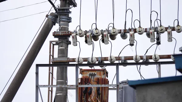
Substation inefficiency is a significant challenge, often resulting from reactive power losses and voltage instability. Engineers deploy capacitor banks to counteract these issues. A capacitor bank in substation operations provides a direct solution to improve system performance. These essential capacitor banks are not just accessories; they are critical capacitor components that directly enhance the performance and financial viability of the grid.
This strategic use of capacitor banks leads to three primary benefits: improved power factor for greater efficiency, stabilized voltage for reliable power delivery, and reduced operational costs.
Key Takeaways
- Capacitor banks make electricity systems work better. They help power flow smoothly and reduce wasted energy.
- These banks fix a problem called low power factor. This means less electricity is wasted, and the system can handle more power.
- Capacitor banks keep voltage steady. This helps protect equipment and makes sure power delivery is reliable.
- Using capacitor banks saves money. They lower electricity bills and make equipment last longer by reducing heat.
- Advanced capacitor banks can also clean up electrical noise. This protects sensitive devices from damage.
The Role of a Capacitor Bank in Substation Power Factor Correction

A capacitor bank in substation operations is a fundamental tool for managing grid efficiency. Its primary function is to correct the system's power factor. This correction directly reduces energy waste and enhances the capacity of the entire substation. Understanding this role begins with defining power factor itself.
Defining Power Factor and Reactive Power
To understand power factor, imagine a glass of beer. The total liquid in the glass is the Apparent Power (kVA)—the total power supplied by the utility. The beer itself is the Real Power (kW), which is the useful power that performs actual work, like running a motor or lighting a bulb. The foam on top is the Reactive Power (kVAR). It takes up space in the glass but does not quench your thirst.
| Analogy | Electrical Term | Description |
|---|---|---|
| 🍺 Beer | Real Power (kW) | The useful power that performs work. |
| ☁️ Foam | Reactive Power (kVAR) | Power required to create magnetic fields. |
| 🍺+☁️ Full Glass | Apparent Power (kVA) | The vector sum of Real and Reactive Power. |
In an electrical system, reactive power is necessary to create the magnetic fields that inductive equipment needs to operate. However, it does no real work. Power factor is the ratio of real power to apparent power (PF = kW / kVA). It is a dimensionless number between -1 and 1 that measures how effectively the system uses electricity. A high power factor means the foam (reactive power) is minimal, and most of the supplied power is doing useful work.
Compensating for Inductive System Loads
Most electrical systems serve numerous inductive loads. These components require reactive power to function. Common examples include:
These loads cause the current to "lag" behind the voltage, resulting in a low power factor. A capacitor bank in substation design counteracts this effect. A capacitor is a component that stores and releases electrical energy. When connected to the grid, capacitor banks generate leading reactive power. This locally supplied reactive power meets the demand of inductive loads. As a result, the utility does not need to transmit as much reactive power across the system, which brings the overall power factor closer to the ideal value of 1.0.
Boosting System Capacity and Reducing Losses
A low power factor forces the utility to supply more apparent power to deliver the same amount of real power. This increases the total current flowing through conductors and transformers. This higher current leads to significant energy losses due to heat, calculated with the formula P = I²R, where P is power loss, I is current, and R is resistance.
Note: These
I²Rlosses, also known as thermal losses, waste energy and generate excess heat. This heat places thermal stress on critical equipment, potentially shortening its lifespan.
By correcting the power factor, capacitor banks reduce the total current required. This reduction has two major benefits:
- Reduced Energy Losses: Lower current dramatically decreases
I²Rlosses. For example, improving the power factor from 0.7 to 0.95 can reduce current by 26% and slash I²R power losses by a remarkable 45%. - Increased System Capacity: With less current flowing to support reactive power needs, the existing infrastructure—including transformers and cables—is freed up. This released capacity allows the substation to serve additional loads without requiring expensive equipment upgrades. Improving the power factor is often the most cost-effective way to resolve thermal overload conditions.
Achieving Near-Unity Power Factor
The ultimate goal of power factor correction is to achieve a near-unity power factor (0.95 to 1.0). Operating below this range introduces significant operational and financial risks. Utilities often penalize industrial and commercial customers for low power factor because it strains the grid and reduces overall efficiency.
⚠️ Risks of Low Power Factor Operating a substation with a low power factor (typically below 0.90) can lead to severe consequences. These include higher electricity bills from utility penalties, overloading of transformers and conductors, and excessive voltage drops that can cause sensitive equipment to malfunction. Some utilities add charges of 15–25% to electricity bills for facilities that fail to maintain a high power factor. These avoidable costs directly impact a facility's financial bottom line. The strategic deployment of capacitor banks mitigates these risks, ensuring both technical and economic stability.
Enhancing Voltage Stability and Power Quality
Beyond power factor, capacitor banks are essential for maintaining voltage stability and overall power quality. A stable voltage profile is critical for the reliable operation of the grid and the longevity of connected equipment. Capacitor banks achieve this by actively managing reactive power and, in advanced configurations, mitigating harmonic distortion.
Providing Reactive Power to Prevent Voltage Drops
Heavy industrial loads, such as large motors and HVAC units, consume significant reactive power to sustain their magnetic fields. When a substation must transmit this reactive power over long distances, the increased current flow causes voltage to drop along the lines. This can lead to instability and poor performance. A capacitor acts as a local source of reactive power. By supplying it close to the load, the capacitor reduces the burden on the transmission system, effectively preventing voltage drops and ensuring a more stable supply.
Ensuring Stable Power Delivery to Consumers
Consistent voltage is not just a preference; it is a requirement for safe and efficient equipment operation. Utilities follow strict standards, like ANSI C84.1, to regulate voltage delivery.
| Range | Tolerance | Description |
|---|---|---|
| Range A | ±5% | The preferred range for normal, efficient system operation. |
| Range B | ±8.3% | An acceptable, short-term range during unusual conditions. |
A capacitor helps keep the system within the preferred Range A. This stability prevents issues like motor overheating and protects sensitive electronics from malfunction. By ensuring equipment receives the correct voltage, a capacitor allows components to perform optimally and reduces the risk of premature failure.
Mitigating Harmonics to Protect Equipment
Modern electrical systems face a growing challenge from harmonic distortion. This "noise" on the electrical waveform degrades power quality and can damage equipment.
⚡️ Sources of Harmonics: Harmonics are primarily caused by non-linear loads, which draw current in abrupt pulses. Common sources include variable frequency drives (VFDs), LED lighting, computer power supplies, and electric vehicle chargers.
While a standard capacitor is excellent for voltage support, it can unintentionally create a resonant circuit with system inductance, amplifying harmful harmonics. To solve this, engineers design advanced capacitor banks with detuning reactors. This design turns the capacitor into a filter. The reactor shifts the circuit's resonant frequency away from common harmonics, preventing amplification and protecting both the capacitor and other sensitive substation components from damaging currents.
Advanced Applications for Capacitor Banks
While shunt capacitors are common, advanced applications use different configurations to solve complex grid challenges. These specialized capacitor banks enhance transmission efficiency and support the integration of modern energy sources.
Using Series Capacitors for Transmission Lines
Engineers use a series capacitor to increase power transfer capability over long distances. Unlike a standard shunt capacitor connected in parallel, a series capacitor is connected directly within the transmission line. This placement reduces the line's overall inductive reactance, which is a form of electrical resistance. Lowering this opposition allows more electricity to flow.
Case studies demonstrate this benefit worldwide. Projects in Sumatera, the Chuanyu Grid in China, and the Wardha Substation in India have all used series compensation. These installations successfully increased the load ability of transmission lines, allowing grids to meet rising power demands without building new lines.
Supporting Long-Distance Renewable Energy Grids
Renewable energy sources like wind and solar are intermittent, creating voltage fluctuations. Capacitor banks are crucial for stabilizing the grid as it integrates these sources. They provide this support in several ways:
- Voltage Support: A capacitor provides reactive power to maintain stable voltage levels during variable generation.
- Buffering Intermittency: They can absorb or release energy to smooth out the power flow from intermittent sources.
- Reducing Losses: They improve system efficiency, ensuring more of the generated renewable energy reaches consumers.
- Enhancing Grid Stability: They help balance supply and demand, making the large-scale integration of renewables more reliable.
The Function of Modern Switching Devices
Switching a capacitor on and off can create large electrical transients that may damage equipment. Modern switching devices manage this process safely. Thyristor-based switches offer significant advantages over older mechanical models.
| Feature | Modern Thyristor Switches | Traditional Mechanical Switches |
|---|---|---|
| Response Time | Near-instantaneous (one cycle) | Slower mechanical action |
| Operation | Switches at zero voltage; no transients | Uses resistors to dampen transients |
| Mechanism | Solid-state electronic; no moving parts | Mechanical contacts in SF6 gas |
| Lifespan | Unlimited switching operations | Limited by mechanical wear |
| Noise | Silent operation | Produces some operational noise |
These advanced thyristor switches allow for real-time, transient-free compensation, making them ideal for grids with rapidly changing loads.
Improving Reliability and Reducing Costs
A capacitor bank in substation operations delivers significant value beyond technical performance. It directly improves system reliability and generates substantial financial returns. By optimizing electrical efficiency, these components lower operational expenditures, extend the life of expensive assets, and help avoid costly utility penalties.
Lowering Thermal Stress on Key Components
A poor power factor forces the electrical distribution system to carry higher current to deliver the same amount of useful power. This excess current is the primary source of thermal stress on substation equipment. The increased current generates significant heat due to resistive losses (I²R losses), causing transformers and switchgear to run at higher operating temperatures.
This added heat poses several risks to critical substation assets:
- It can cause transformers to overload, pushing them beyond their designed thermal capacity.
- It accelerates the degradation of insulation materials, which is a primary cause of equipment failure.
- It leads to higher energy losses, increasing operational costs.
A capacitor provides a local source of reactive power, reducing the total current flowing through the system. This simple correction lowers the operating temperature of transformers and conductors. The impact of this temperature reduction on equipment longevity is profound.
💡 The 10°C Rule: A widely accepted guideline in the electronics and electrical industries states that for every 10°C (18°F) reduction in operating temperature, the functional lifespan of the equipment can effectively double.
By lowering thermal stress, capacitor banks not only reduce energy waste but also serve as a crucial tool for asset management, extending the life of multi-million dollar substation components.
The Financial Case for Power Factor Correction
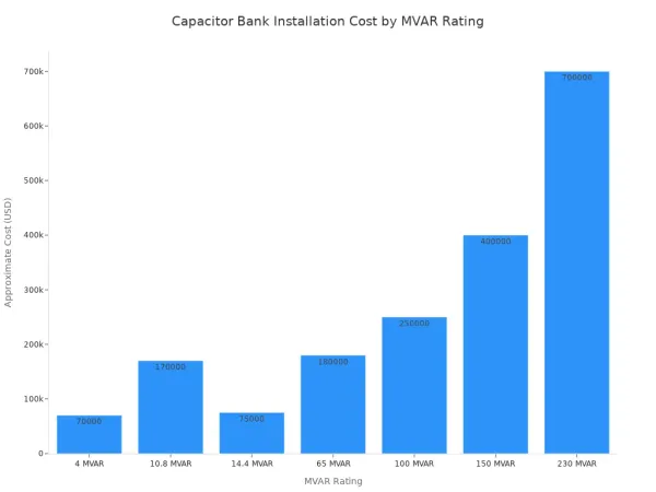
Installing capacitor banks represents a capital investment, but one that offers a clear and often rapid return. The cost of a capacitor varies based on its MVAR rating, voltage level, and design type (e.g., indoor metal-clad vs. outdoor fuseless).
Here are some approximate installation costs for different capacitor bank sizes:
| MVAR Rating | Voltage | Type | Approximate Cost |
|---|---|---|---|
| 4 MVAR | 12kV | Metal-clad switchgear | ~$70,000 |
| 10.8 MVAR | 34.5kV | Metal-clad switchgear | ~$170,000 |
| 65 MVAR | 138kV | Fuseless outdoor | ~$180,000 |
| 150 MVAR | 345kV | Fuseless outdoor | ~$400,000 |
While these initial costs may seem significant, the financial savings quickly justify the investment. Businesses often see an immediate reduction in energy costs of 20-25%. The payback period is typically short, making it a highly attractive financial decision.
| Scenario | Monthly Savings | Investment Cost | Payback Period |
|---|---|---|---|
| Low Voltage Capacitor Installation (Example 1) | $297/month | $7,000 | ~2 years |
| Low Voltage Capacitor Installation (Example 2) | $208/month | $5,700 | ~2.3 years |
In many cases, manufacturers have paid off their investment in as little as 18 months while securing annual savings ranging from $5,000 to over $20,000.
Avoiding Utility Penalties and Lowering Energy Bills
Utilities penalize customers with low power factor because it strains the grid and forces them to generate or transmit non-productive reactive power. These penalties are a major operational expense for industrial and large commercial facilities. Utilities use several methods to charge for poor power factor:
- Billing for Apparent Power (kVA): Some utilities bill for kVA demand instead of just real power (kW). Since kVA includes reactive power, a low power factor directly increases the billed amount.
- Adjusting Billed Demand: Many utilities set a minimum power factor (e.g., 90% or 95%). If a customer falls below this, their billed kW demand is artificially increased, resulting in a higher bill.
- Charging for Reactive Demand (kVAR): Other utilities directly charge for kVARs when they exceed a certain percentage of the kW demand, adding a separate line item to the bill.
💰 The Cost of Inefficiency: These penalties are not trivial. A facility with an 85% power factor could be billed for 900 kVA of demand, even if its real power peak was only 850 kW. This effectively creates a "phantom" charge for inefficiency. By installing a capacitor to correct the power factor, facilities can eliminate these penalties and significantly lower their monthly electricity bills.
A capacitor bank in substation operations is far more than an accessory. It is an essential asset for grid management. These capacitor banks deliver key benefits. They correct power factor for greater efficiency and stabilize voltage for better power quality. A capacitor also reduces thermal stress, which improves equipment reliability. The function of the capacitor is central to a modern grid.
As the grid evolves, automated capacitor systems will play an indispensable role. They will help build a more efficient, reliable, and cost-effective power network for the future.
FAQ
What is the main job of a capacitor bank?
A capacitor bank's primary job is to improve power factor. It acts as a local source of reactive power for the grid. This function reduces the total current flowing through the system, which increases efficiency and frees up capacity on transformers and conductors.
Can a capacitor bank cause problems?
Yes, a standard capacitor can create issues. It may form a resonant circuit with system inductance, which amplifies harmful harmonics.
Engineers prevent this by adding a detuning reactor. This component turns the capacitor bank into a filter, protecting the grid and other sensitive equipment from damage.
How long do substation capacitor banks last?
Capacitor banks are durable assets. With proper maintenance and protection from transients and harmonics, these components can have a service life of 20 years or more. Their longevity makes them a reliable, long-term investment for improving substation performance and reducing operational costs.


