A Technical Review of 6 Pin DPDT Switch Internal Plates
A 6 pin dpdt switch internal plates system uses two single-pole double-throw mechanisms combined. Engineers and technicians
A 6 pin dpdt switch internal plates system uses two single-pole double-throw mechanisms combined. Engineers and technicians value the dpdt design for its ability to control two circuits at once. The toggle switch maintains one of two positions, allowing the user to select between two circuit paths or power sources. The dpdt plates connect each pole to one of two throws, supporting tasks such as signal routing, polarity reversal, or input swapping. Hobbyists often use dpdt switches for precise control in electronic projects. The arrangement and material of the internal plates affect performance and reliability.
Key Takeaways
- A 6 pin DPDT switch controls two circuits simultaneously using six terminals, enabling versatile electrical switching.
- The internal plates move together via a snap-action mechanism, ensuring fast, reliable, and precise switching.
- Materials like brass, copper, and silver plating improve conductivity and durability, extending switch lifespan.
- Different actuator types, such as toggle and pushbutton, affect how the internal plates move and the switch's feel.
- DPDT switches are widely used in motor control, audio routing, power source selection, and industrial applications for dependable dual-circuit control.
6 Pin DPDT Switch Overview
What Is a DPDT Switch
A dpdt switch, or double pole double throw switch, controls two separate circuits at the same time. Each pole operates independently, but both move together when the toggle switch is activated. This design allows the user to route current through two different paths for each circuit. The dpdt toggle switch is often found in applications that require reversing polarity, switching between power sources, or controlling two devices at once.
The dpdt switch stands out from other types of toggle switches due to its unique configuration. The table below compares common switch types:
| Switch Type | Control Capability | Number of Circuits Controlled | Output Options | Typical Use | Synchronized Switching |
|---|---|---|---|---|---|
| SPST | Simple ON/OFF | 1 | 1 | Basic light or power control | No |
| SPDT | Switches one input between two outputs | 1 | 2 | Signal routing, basic selector switches | No |
| DPDT | Switches two circuits between two outputs | 2 | 2 per circuit (4 total) | Motor reversing, dual system control | Yes |
A dpdt switch combines two single pole double throw switches into one unit. This feature enables synchronized switching of two circuits, which is not possible with simpler toggle switch types.
Double Pole Double Throw Function
The double pole double throw function means the switch has two poles and each pole can connect to one of two throws. In a 6 pin dpdt switch, each pole has three terminals: common, normally open, and normally closed. The toggle switch moves both poles at once, changing the connection from one throw to the other.
Note: The 6-pin configuration is standard in the electronics industry. Each pin serves a specific role in the circuit.
- The six pins correspond to:
- Two commons (inputs)
- Two normally open contacts (outputs)
- Two normally closed contacts (outputs)
When the toggle switch is flipped, the dpdt changes the path of current for both circuits. This action allows for functions such as reversing a DC motor or switching between two audio sources. The dpdt can handle significant electrical loads, with typical ratings of 20A at 120/277V AC. Standard dimensions for a 6 pin dpdt switch are approximately 1.3 x 0.8 x 2.1 inches, with a mounting hole size of 1/2 inch (12 mm).
| Feature | Specification |
|---|---|
| Dimensions (in) | 1.3 x 0.8 x 2.1 |
| Mounting hole size | 1/2 inch (12 mm) |
| Pin count | 6 screw terminals |
| Current rating | 20A @ 12V DC, 15A @ 250V AC |
The dpdt toggle switch provides reliable, synchronized control for two circuits, making it a versatile component in many electrical and electronic systems.
6 Pin DPDT Switch Internal Plates
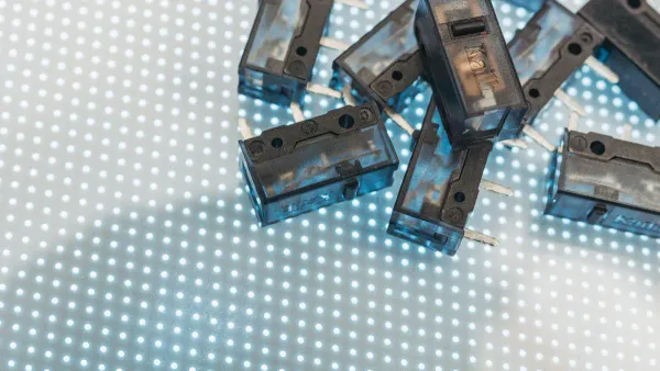
Plate Layout
Engineers design the 6 pin dpdt switch internal plates to bridge specific terminals inside the switch. Each plate connects a common terminal to either a normally open or normally closed contact. The plates sit parallel to each other, separated by insulating barriers. This arrangement allows the dpdt mechanism to control two independent circuits at the same time. When the actuator moves, the plates slide or pivot, making or breaking connections between the terminals.
A typical dpdt switch contains two sets of plates. Each set operates one pole of the switch. The plates align with the six pins on the base. The following diagram shows a simplified layout:
[ C1 ]---[ Plate 1 ]---[ NO1 ]
[ C1 ]---[ Plate 1 ]---[ NC1 ]
[ C2 ]---[ Plate 2 ]---[ NO2 ]
[ C2 ]---[ Plate 2 ]---[ NC2 ]
The plates move in response to the actuator, such as a toggle or micro-switch lever. This movement ensures reliable switching between circuit paths. The design of the 6 pin dpdt switch internal plates supports precise control in applications like audio routing, motor direction control, and micro-switch logic circuits.
Materials and Coatings
Manufacturers select materials for the 6 pin dpdt switch internal plates based on conductivity, durability, and resistance to corrosion. Brass and copper serve as common base materials. These metals offer excellent electrical conductivity and mechanical strength. Some dpdt switches use silver plating on the contact surfaces. Silver improves conductivity and reduces contact resistance.
A micro-switch often features plates with a thin layer of nickel or gold. These coatings protect against oxidation and wear. The table below summarizes typical materials and coatings:
| Material | Purpose | Common Use in DPDT Switches |
|---|---|---|
| Brass | Base plate, strength | General switching |
| Copper | High conductivity | Signal routing |
| Silver | Low resistance, plating | Contact surfaces |
| Nickel | Corrosion protection | Micro-switch contacts |
| Gold | Premium protection | High-reliability switches |
Engineers choose coatings based on the expected environment and electrical load. For example, a micro-switch in a humid environment may require gold plating to prevent corrosion. The selection of materials and coatings directly affects the performance and lifespan of the 6 pin dpdt switch internal plates.
Mounting and Protection
Manufacturers mount the internal plates securely inside the dpdt switch housing. The plates attach to molded plastic supports or insulated frames. This structure prevents movement or misalignment during operation. Engineers design the housing to shield the plates from dust, moisture, and mechanical shock.
A micro-switch often includes a sealed enclosure. This feature protects the plates and contacts from contaminants. Some dpdt switches use rubber gaskets or epoxy seals for added protection. The mounting system ensures that the plates maintain proper alignment with the actuator and terminals.
Technicians value the robust mounting and protection features in the 6 pin dpdt switch internal plates. These features reduce the risk of failure and extend the service life of the switch. Proper mounting also supports consistent performance in demanding applications, such as industrial controls and micro-switch logic circuits.
Tip: Always inspect the housing and mounting system before installing a dpdt switch. A secure enclosure helps maintain reliable operation and protects the internal plates from damage.
DPDT Internal Mechanism
Actuator Types
Engineers use several actuator types in dpdt switches to control the movement of internal plates. The most common actuator types include rocker, toggle, pushbutton, illuminated rocker, and tactile pushbutton. Each actuator type creates a unique motion that influences how the plates move inside the switch.
- Rocker actuators produce a rocking motion. This motion causes the internal plates to pivot between contact points.
- Toggle actuators use a lever mechanism. The lever shifts the plates from one position to another, changing the circuit path.
- Pushbutton actuators operate with a linear press. When pressed, the plates move straight down to make or break connections.
- Illuminated rocker actuators combine visual feedback with the rocking action. The plates move in response to the actuator, and the illumination signals the switch status.
- Tactile pushbuttons provide a snap-action mechanism. The plates move quickly and return to their original position after actuation.
Momentary actuators, such as tactile pushbuttons and illuminated rockers, use a snap-action mechanism to return the plates to their default state. Maintained actuators, like some rocker or toggle switch designs, keep the plates in the switched position until the user actuates the switch again. The choice of actuator type affects the feel, speed, and reliability of the dpdt toggle switch.
Plate Movement
The internal plates in a dpdt switch move in response to the actuator. When a user flips the toggle switch or presses a pushbutton, the actuator transfers force to the plates. The plates slide, pivot, or snap into place, depending on the actuator type and the micro-switch design.
A snap-action mechanism ensures quick and precise movement. This mechanism reduces wear and improves the switch's lifespan. In a micro-switch, the plates often move with a distinct snap, making or breaking contact instantly. Springs inside the switch help maintain the correct position of the plates. These springs also support the snap-action mechanism, providing tactile feedback and ensuring reliable operation.
The dpdt toggle switch uses a lever to move both sets of plates at once. This synchronized movement allows the switch to control two circuits with a single action. The micro-switch design keeps the plates aligned with the terminals, preventing misalignment and electrical faults.
Contact Points
Contact points in a dpdt switch play a critical role in ensuring reliable electrical connection and disconnection. Manufacturers use brass terminals with silver plating to reduce contact resistance and enhance durability. The contact resistance remains low, typically below 50 milliohms, which supports efficient current flow.
Springs inside the micro-switch keep the toggle switch in the correct position. These springs also maintain pressure on the contact plates, ensuring stable operation. Electrical contacts, often called blades, control two circuits each. Each blade connects to three pins: common, ON, and ON. Terminal blocks provide secure connections to external circuits, while the housing protects internal components and offers mechanical support.
The dpdt switch features a high-reliability electrical sealing structure. This design maintains consistent electrical connection and disconnection through precise mechanical action. The switch supports multiple contact arrangements, such as ON-ON and ON-OFF-ON, to meet different application needs. The electrical life of a dpdt toggle switch often exceeds 10,000 cycles, with mechanical life reaching 100,000 cycles.
| Design Aspect | Description |
|---|---|
| Contact Material | Brass terminals with silver plating to reduce contact resistance and enhance durability |
| Contact Resistance | Maximum 50 milliohms, ensuring low resistance at contact points |
| Mechanical Features | Use of springs internally to maintain correct contact positioning |
| Contact Arrangements | Multiple configurations (ON-ON, ON-OFF-ON, etc.) to support reliable switching functions |
| Electrical Life | Rated for at least 10,000 electrical cycles and 100,000 mechanical cycles |
| Application Suitability | Designed for demanding applications requiring reliable connection and disconnection |
Note: The micro-switch structure and snap-action mechanism work together to provide fast, reliable switching. This combination ensures that the dpdt toggle switch performs well in demanding environments.
Double Pole Double Throw Circuit Paths
ON-ON Configuration
The ON-ON configuration in a dpdt switch allows users to toggle between two active circuit paths. This setup does not include an off position. Each pole connects its common terminal to either the normally open (NO) or normally closed (NC) contact, depending on the switch position. The dpdt switch uses six terminals: two poles as inputs and four throws as outputs. Only one path per pole remains active at any time.
- Reversing the direction of DC motors by changing current polarity.
- Switching between two power sources, such as a battery and a wall outlet.
- Audio routing to select between different inputs or outputs.
- Model railroad track polarity control for changing train direction.
- Lighting control for selecting different circuits or brightness levels.
- Manual override in automation systems for switching between operating modes.
The ON-ON dpdt configuration is popular because it enables seamless switching between two circuits or modes. Users often choose toggle or rocker styles for tactile feedback and ease of use. The ability to control two circuits at once makes the dpdt switch ideal for applications that require reliable and synchronized switching.
| Application | Function Provided by DPDT ON-ON |
|---|---|
| DC Motor Control | Polarity reversal |
| Power Source Selection | Switch between supplies |
| Audio Routing | Input/output selection |
| Model Railroads | Track direction change |
| Lighting | Circuit or brightness selection |
Tip: The ON-ON dpdt switch ensures that one circuit path always remains active, which is essential for continuous operation in many systems.
ON-OFF-ON Configuration
The ON-OFF-ON configuration in a dpdt switch introduces a center off position between the two ON states. In this setup, both poles disconnect from their outputs when the switch sits in the middle position. This feature increases versatility by allowing users to completely interrupt the circuit between active states. The dpdt switch in ON-OFF-ON mode provides safer operation and more control options, especially in designs that require a clear off state.
Circuit designers often use the ON-OFF-ON dpdt switch for applications where disconnecting the load is necessary. For example, in motor control, the center off position stops the motor without switching to the opposite direction. This configuration also suits lighting systems that need a true off state between brightness levels or modes.
The ON-OFF-ON dpdt switch balances simplicity and functionality. It supports a wide range of circuit designs, offering both active switching and a reliable off position.
Note: The center off position in the ON-OFF-ON dpdt switch helps prevent accidental activation and provides an extra layer of safety in electrical systems.
Performance and Applications
Reliability Factors
The reliability of a 6 pin DPDT switch depends on several key factors. Engineers often select switches based on their ability to withstand demanding environments and frequent use. The following table highlights the most important reliability factors:
| Factor | Description |
|---|---|
| Contact Rating | Maximum voltage and current the switch can safely handle; prevents electrical damage. |
| Environmental Conditions | Temperature, humidity, vibration, dust, and moisture; impacts durability and performance. |
| Mounting Options | Physical orientation and mounting method; affects stability and ease of maintenance. |
| Actuation Force | Required force to toggle the switch; influences user experience and mechanical wear. |
Switches with locking mechanisms, such as bayonet or push-lock couplings, prevent accidental toggling. This feature proves essential in high-vibration or safety-critical environments. Rocker and slide actuators also contribute to reliability by providing smooth operation and secure position holding. The micro-switch design, with its snap-action mechanism, ensures consistent contact and reduces wear over time.
Manufacturers rate many 6 pin DPDT switches for 20,000 mechanical cycles. Proper installation and soldering techniques, such as cleaning pads and using correct temperatures, extend the lifespan of the switch. Regular inspection and cleaning remove dirt and oxidation, maintaining electrical connectivity and mechanical integrity.
Tip: Using protective caps and storing unused switches in dry environments helps prevent contamination and oxidation, further increasing reliability.
Typical Uses
6 pin DPDT switches serve a wide range of applications in both consumer electronics and industrial equipment. Their ability to control two circuits at once makes them valuable in complex systems. Common uses include:
- Automotive systems, such as heated seats, power windows, rear window defoggers, and battery disconnects.
- Household appliances, including clothes dryers, electric ranges, and air conditioning units.
- Industrial control panels, handling machines, HVAC systems, and electrical equipment control.
- Instrumentation front panels, power supplies, computers, telecommunications, and audio/visual equipment.
- Toys, game consoles, medical devices, and military equipment often use micro-switch types for reliable switching.
- Push button switches with multiple contacts, including micro-switch DPDT types, appear in testing instruments and specialized equipment.
The micro-switch structure allows for simultaneous switching of multiple circuits or changing circuit paths. This capability is essential in applications that require precise control and high reliability.
A 6 pin DPDT toggle switch combines two SPDT mechanisms, enabling control of two circuits with six terminals. The snap-action mechanism inside the toggle switch ensures rapid and reliable switching, while contact materials and environmental sealing contribute to durability. Understanding the internal structure of a toggle switch helps technicians troubleshoot wiring errors, identify faults, and verify correct operation using tools like multimeters. Those interested in advanced applications can explore projects such as motor reversing, power source switching, and automation using toggle switch relay modules. Hands-on learning with toggle switch wiring, safety practices, and microcontroller integration offers valuable experience for engineers and hobbyists.
- Key points:
- Two independent circuits controlled by one toggle switch.
- Snap-action mechanism for consistent performance.
- Six terminals for flexible wiring and troubleshooting.
- Advanced projects include automation, robotics, and power management.
FAQ
What does DPDT stand for?
DPDT means Double Pole Double Throw. This switch type controls two separate circuits. Each pole connects to two different outputs, allowing users to change circuit paths easily.
Why do manufacturers use silver plating on internal plates?
Silver plating improves electrical conductivity. It also reduces contact resistance and helps prevent corrosion. Engineers select silver for switches that need reliable performance and long service life.
How can someone test a 6 pin DPDT switch?
Technicians use a multimeter to check continuity between terminals. They move the actuator and observe changes in the circuit path. This method verifies correct operation and identifies faulty contacts.
Where do engineers use 6 pin DPDT switches most often?
Engineers install these switches in motor control panels, audio equipment, and automation systems. The DPDT design supports polarity reversal, signal routing, and dual-circuit switching in many devices.