

What Is a Zener Diode and How Does It Work
A Zener diode is a special semiconductor device engineered to operate in reverse. Its primary purpose is to mainta
A Zener diode is a special semiconductor device engineered to operate in reverse. Its primary purpose is to maintain a precise, constant voltage when a specific reverse voltage is reached. You can think of this Zener diode as a pressure relief valve; it allows current to flow backward to regulate voltage. Its role in modern electronics is significant, with a growing market forecast:
| Metric | Value |
|---|---|
| Market Size (2024) | USD 784.06 Million |
| Projected Market Size (2033) | USD 1237.35 Million |
| CAGR (2026–2033) | 5.2% |
Key Takeaways
- A Zener diode keeps voltage steady. It works by letting current flow backward when the voltage reaches a certain point.
- Zener diodes act like normal diodes when current flows forward. They regulate voltage only when current flows backward.
- Key features of a Zener diode are its Zener Voltage (Vz), Power Rating (Pz), and Zener Impedance (Zz). These help you choose the right one.
- Zener diodes are good for voltage regulation. They protect circuits from too much voltage and shape electrical signals.
- A series resistor is important in a Zener circuit. It limits current and protects the diode from damage.
Understanding the Diode Zener Operation
To appreciate the unique role of a Zener diode, we must examine its behavior under two different electrical conditions: forward bias and reverse bias. While it acts like a standard diode in one direction, its specialized design shines when the voltage is applied in reverse.
Forward-Bias Behavior
When a Zener diode is forward-biased, it behaves just like a standard silicon diode. The anode (positive terminal) connects to a positive voltage source, and the cathode (negative terminal) connects to a negative source. This setup reduces the diode's internal potential barrier. Current flows easily through the device once the applied voltage overcomes this barrier.
This forward voltage drop is typically around 0.6V to 0.7V, a characteristic shared with most common silicon diodes. In this state, the Zener diode simply conducts current in the forward direction and does not perform its voltage regulation function.
Reverse-Bias and Zener Breakdown
The true purpose of a Zener diode is revealed in its reverse-bias operation. Here, the connections are flipped: the cathode connects to the positive voltage source, and the anode connects to the negative source. This configuration normally blocks current flow in a standard diode. However, a Zener diode is engineered differently.
As the reverse voltage increases, it eventually reaches a specific point called the Zener Voltage (Vz). At this voltage, a controlled breakdown occurs, and the diode begins to conduct a significant amount of current in reverse. This process is known as the Zener effect.
What is the Zener Effect? The Zener effect is a quantum mechanical phenomenon. In heavily doped semiconductors, the depletion region is very narrow. A strong electric field from the reverse voltage allows electrons to "tunnel" directly from the valence band to the conduction band. This creates numerous free charge carriers, causing a sharp increase in reverse current without damaging the diode.
This controlled breakdown is distinct from the destructive avalanche breakdown that occurs in standard diodes at much higher voltages. The Zener diode is specifically designed to operate in this breakdown region continuously and reversibly.
| Characteristic | Zener Breakdown | Avalanche Breakdown |
|---|---|---|
| Primary Cause | Strong electric field (tunneling) | High-energy particle collisions |
| Breakdown Voltage | Lower (typically < 6V) | Higher (typically > 6V) |
| Depletion Region | Thin | Thick |
| Doping Level | Heavily doped | Lightly doped |
| Junction State | Recovers after voltage is removed | Can be permanently damaged |
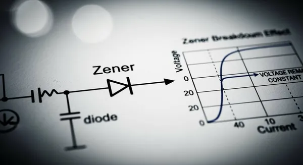
The Zener V-I Characteristic Curve
The V-I (Voltage-Current) characteristic curve provides a clear visual summary of a Zener diode's behavior.
- Forward-Bias Region (Quadrant I): The curve looks identical to a standard diode. Current remains near zero until the voltage reaches approximately +0.7V, after which it rises exponentially.
- Reverse-Bias Region (Quadrant III): As the reverse voltage (negative) increases from 0V, only a very small leakage current flows. This continues until the voltage reaches the Zener voltage (-Vz).
- Breakdown Region (The "Knee"): At -Vz, the curve turns sharply downward, forming a "knee." Beyond this point, the voltage across the diode remains almost perfectly constant at Vz, even as the reverse current increases dramatically. This vertical line on the graph represents the voltage regulation region.
The sharpness of this knee is a key performance indicator. A sharp, well-defined knee signifies a low internal impedance and excellent voltage stability. A rounded knee, in contrast, indicates higher impedance and less precise regulation. For a common 5.1V Zener diode, this breakdown is very distinct, making it a reliable component for holding a steady 5.1V output.
Key Zener Diode Parameters
To use a Zener diode effectively, you must understand its key datasheet parameters. These values define the diode's performance limits and its suitability for a specific application. Selecting the right component requires a close look at these three critical specifications.
Zener Voltage (Vz)
The Zener Voltage (Vz) is the most important parameter. It defines the nominal reverse voltage at which the diode enters its breakdown region and begins to regulate. Manufacturers produce Zener diodes with a wide range of standard Vz values, such as 3.3V, 5.1V, 9.1V, and 12V. This allows engineers to choose a diode that precisely matches the voltage level required for their circuit. The tolerance of this voltage is also specified, indicating how much the actual Vz might vary from the nominal value.
Power Dissipation Rating (Pz)
The Power Dissipation rating (Pz) tells you the maximum amount of power the diode can handle without being damaged. Since the Zener diode converts electrical energy into heat during operation, this rating is crucial for reliability. The power dissipated is calculated using the formula Pz = Vz × I, where Vz is the Zener voltage and I is the current flowing through the diode. For instance, a 5.1V Zener with 0.11A of current flowing through it dissipates 0.561W (561mW).
Safety Tip 💡 Always choose a Zener diode with a power rating higher than your calculated maximum dissipation. For a 561mW calculation, selecting a 1W or 1.3W diode provides a safe operating margin.
Zener Impedance (Zz)
Zener Impedance (Zz) is the small amount of internal resistance the diode exhibits when operating in the breakdown region. An ideal Zener would have zero impedance, meaning its voltage would not change at all, regardless of the current. In reality, all Zener diodes have some impedance. A lower Zener impedance results in better voltage regulation because the voltage across the diode remains more stable as the current fluctuates. On a V-I curve, a low Zz corresponds to a very sharp, nearly vertical line in the breakdown region.
Zener Diode Voltage Regulation
The most common application for a Zener diode is voltage regulation. By leveraging its unique reverse breakdown characteristic, it can create a simple yet effective circuit known as a shunt regulator. This circuit provides a stable output voltage from a fluctuating or noisy input source, making it a cornerstone of power supply design.
The Basic Regulator Circuit
A basic Zener regulator circuit is straightforward. It consists of just two main components working together: a series resistor and the Zener diode itself.
- Input Voltage (Vs): This is the unregulated power source, which must be higher than the Zener voltage (Vz).
- Series Resistor (Rs): This resistor is connected between the input source and the Zener diode. It serves two critical functions. First, it allows enough current to flow for the Zener to enter its breakdown region. Second, it protects the Zener diode from drawing excessive current, which could cause damage.
- Zener Diode (Dz): The Zener is connected in reverse bias, parallel to the load. Its cathode connects to the positive side of the circuit.
- Load (RL): This is the component or circuit that requires the stable, regulated voltage.
Here is a simple representation of the circuit layout:
      +----[ Rs ]----+----o Vout
      |              |
     Vs             ---
      |             / \  Dz
      |              |
      +--------------+----o Gnd
In this setup, the output voltage (Vout) is taken directly across the Zener diode, ensuring it remains locked at the Zener voltage (Vz).
How It Stabilizes Voltage
A Zener diode stabilizes voltage by acting as a variable current shunt. Once the input voltage is high enough to put the Zener into its breakdown region, the magic happens.
- The Zener diode is designed to operate in reverse bias.
- It maintains a constant output voltage across the load.
- The input voltage must always exceed the Zener voltage (Vz) for regulation to work.
When the reverse voltage reaches the Zener breakdown point, the diode starts conducting significant current. This conduction clamps the voltage across it at a nearly constant level. Any excess voltage from the source is dropped across the series resistor (Rs). The diode effectively shunts, or diverts, any unneeded current to the ground, keeping the voltage across the load steady.
Calculating the Series Resistor (Rs) Choosing the correct value for the series resistor is essential for the circuit to function properly. You can calculate it with a simple formula.
- Determine Total Current (Itotal): First, add the current your load requires (IL) and the minimum current the Zener needs to stay in breakdown (Iz_min). A good rule of thumb is to set Iz_min to 10% of the load current.
Itotal = IL + Iz_min- Calculate the Resistor Value (Rs): Use Ohm's law. The voltage across the resistor is the input voltage (Vs) minus the Zener voltage (Vz).
Rs = (Vs - Vz) / ItotalExample: Let's say you have a 12V input, need a stable 5.1V output for a load drawing 50mA.
Iz_min = 10% of 50mA = 5mAItotal = 50mA + 5mA = 55mARs = (12V - 5.1V) / 0.055A = 6.9V / 0.055A ≈ 125Ω
Managing Input and Load Changes
A Zener regulator's true value is its ability to handle fluctuations. It maintains a stable output even when the input voltage varies or the load's current demand changes.
Scenario 1: Input Voltage Increases If the input voltage (Vs) rises, the total current flowing through the series resistor (Rs) also increases. The load still only needs its required current. The Zener diode automatically absorbs this extra current, shunting more of it to the ground. While the current through the Zener changes, the voltage across it (Vz) remains almost perfectly constant. This ensures the load continues to receive a stable voltage.
Scenario 2: Load Current Decreases Imagine the load goes into a low-power state and draws less current. This leaves more current available in the circuit. Again, the Zener diode compensates. It simply draws this now-surplus current and shunts it to the ground. The voltage across the parallel combination of the Zener and the load stays locked at Vz.
This dynamic self-adjustment makes the Zener diode an excellent choice for providing a stable reference voltage or for powering small-scale circuits where reliability is key.
Common Zener Diode Applications
The unique properties of Zener diodes make them valuable in many electronic circuits. Their ability to provide stable voltage and protection is fundamental. At a professional level, companies like Nova Technology Company (HK) Limited, a HiSilicon-designated solutions partner, leverage deep expertise in chip-level design and system integration. Their work often involves protecting sensitive ICs and creating stable power environments where components like Zener diodes play a critical role. Let's explore some of the most common applications.
Voltage Reference Circuits
A primary use for a Zener diode is creating a stable voltage reference. In many circuits, especially in power supplies and measurement instruments, a known and constant voltage is needed for comparison. The Zener diode's consistent breakdown voltage (Vz) provides this reference point. While effective, it's important to know how it compares to other technologies like bandgap references, which are common in high-precision ICs.
Zener vs. Bandgap Reference: A Quick Comparison Bandgap references are preferred for high-precision, low-power applications, while Zener references are excellent for general-purpose use where cost and simplicity are key.
| Feature | Zener Reference | Bandgap Reference |
|---|---|---|
| Accuracy | Moderate | High |
| Power Consumption | Higher | Very Low |
| Cost | Low | Higher |
| Complexity | Simple to implement | More complex |
| Key Takeaway | Great for cost-sensitive, general-purpose regulation. | Ideal for precision, battery-powered devices. |
Overvoltage Protection
Zener diodes are excellent for protecting sensitive components, like microcontrollers, from voltage spikes. The protection circuit is simple but effective.
- A series resistor is placed on the input line.
- The Zener diode is connected in parallel with the component to be protected, with its cathode facing the positive line.
- During normal operation, the input voltage is below Vz, and the Zener is inactive.
- If a voltage surge occurs that exceeds Vz, the Zener begins to conduct. It shunts the excess current to the ground, clamping the voltage at a safe level (e.g., 5.1V for a 5V component).
Unlike a fuse, which is a one-time-use device, a Zener diode automatically resets once the voltage returns to normal. This makes it a reliable, self-recovering guard for your electronics.
Waveform Clipping and Clamping
Zener diodes can also modify AC signals. This application is known as clipping or clamping. By placing a Zener diode in an AC circuit, you can "clip" off parts of the waveform that exceed its Zener voltage.
- Single-Sided Clipping: A single Zener diode will limit either the positive or negative half of an AC waveform.
- Double-Sided Clipping: Using two Zener diodes connected back-to-back in series allows you to clip both the positive and negative peaks. This is a simple way to convert a sine wave into a rough square wave.
This technique is useful in signal processing and for protecting circuits from excessive AC voltage swings.
A Zener diode is a unique component. It uses its stable reverse breakdown voltage to provide reliable voltage regulation and protection. This function makes it a fundamental building block in power supplies, protection circuits, and voltage reference designs. As technology advances, its role continues to expand into new areas.
The Future is Zener! 🚀 Emerging applications show the Zener diode's lasting importance:
- Electric Vehicles (EVs): Optimized diodes ensure battery safety and longevity in high-voltage systems.
- Smart Grids: Diodes with real-time voltage sensing help manage power distribution.
- Renewable Energy: Custom Zener diodes provide stable voltage in solar and wind systems.
Mastering the Zener diode is essential for anyone serious about electronics. Its simple principle and powerful applications make it a key component in both classic and future technologies.
FAQ
Can I use a Zener diode as a regular diode?
Yes, you can. When forward-biased, a Zener diode behaves just like a standard diode. It allows current to flow with a typical voltage drop of about 0.7V. However, its special voltage regulation feature only works when it is reverse-biased.
What happens if the input voltage is lower than the Zener voltage?
If the input voltage is below the Zener voltage (Vz), the diode will not enter its breakdown region. It will act like an open switch, blocking reverse current flow. The circuit will not regulate the voltage under this condition.
How do I choose the right Zener diode?
To select the correct Zener diode, you must consider three main factors:
- Zener Voltage (Vz): This must match your desired output voltage.
- Power Rating (Pz): It must be able to handle the circuit's power dissipation.
- Load Requirements: The diode must suit your load's current needs.
Why is the series resistor so important?
The series resistor (Rs) is critical for two reasons. First, it limits the current to a safe level, protecting the Zener diode from damage. Second, it drops the excess voltage between the input source and the stable Zener voltage.


