The Complete Guide to PCB Assembly Process
The pcb assembly process brings your electronic designs to life by mounting components onto a pcb. You start with a solid pcb design process, then move through steps like DFA, SMT, THT, soldering, inspection, and testing
The pcb assembly process brings your electronic designs to life by mounting components onto a pcb. You start with a solid pcb design process, then move through steps like DFA, SMT, THT, soldering, inspection, and testing. This assembly is crucial for devices you use every day. The pcb assembly market reached about USD 90 billion in 2024, showing its huge role in modern electronics.
|
Statistic Description |
Value/Detail |
|---|---|
|
PCB Assembly Market Value (2024) |
USD 90 billion |
|
Projected Market Value (2033) |
USD 152.46 billion |
|
CAGR (2025-2033) |
5.8% |
Key Takeaways
-
PCB assembly turns bare circuit boards into working devices by attaching components through steps like soldering and testing.
-
Surface Mount Technology (SMT) and Through-Hole Technology (THT) serve different needs; SMT is fast and compact, while THT offers strong, durable connections.
-
Good design for assembly (DFA) and careful solder paste application reduce errors and improve reliability in the assembly process.
-
Inspection methods like Automated Optical Inspection (AOI) and X-ray help catch defects early and ensure high-quality circuit boards.
-
Choosing a certified and experienced PCB assembly partner with strong quality control and communication leads to better results and fewer delays.
PCB Assembly Process Overview
What Is PCB Assembly?
You can think of pcb assembly as the step that turns a bare printed circuit board into a working electronic device. The pcb assembly process involves attaching electronic components to the board. This process uses both machines and skilled workers. You start with a pcb design process, which includes creating a schematic, making a bill of materials, and designing the layout. After that, the pcb manufacturing process creates the bare board with copper pathways.
Here is a simple breakdown of how printed circuit board assembly works:
-
PCB Manufacturing: You get the bare printed circuit boards ready.
-
Solder Paste Application: You apply solder paste to areas where components will go.
-
Component Placement: Machines or people place parts onto the board.
-
Soldering: The process secures components to the board, often using reflow ovens.
-
Inspection and Testing: You check for errors using tools like AOI and X-ray.
-
Through-Hole Soldering: Some parts need to be inserted and soldered by hand or machine.
You end up with a fully assembled and functional board, called a PCBA. The difference between a pcb and a PCBA is simple: the pcb is just the board, while the PCBA has all the parts attached and works as intended.
Why PCB Assembly Matters
You rely on printed circuit board assembly for almost every electronic device you use. The process allows you to create compact, reliable, and high-performance products. The pcb assembly process supports miniaturization, so you can have smartphones, laptops, and wearables that fit in your pocket. It also makes mass production possible, which keeps costs down.
Printed circuit boards appear in many industries:
-
Consumer electronics (phones, tablets)
-
Automotive systems (car computers, sensors)
-
Medical devices (monitors, pacemakers)
-
Industrial equipment (robots, automation)
-
Aerospace and defense (navigation, communication)
The pcb manufacturing process and assembly steps ensure that circuit boards meet strict quality standards. You benefit from high reliability, strong performance, and the ability to customize boards for special uses. The process also includes testing methods like in-circuit testing and environmental testing, so your devices work well in real-world conditions.
Tip: Understanding the pcb assembly process helps you make better choices when designing, sourcing, or troubleshooting electronic products.
Printed Circuit Board Assembly Types
Printed circuit boards come in different assembly types. Each type fits certain needs in electronics. You should know the main types: Surface Mount (SMT), Through-Hole (THT), and Mixed Technology. These methods help you choose the right process for your project.
Surface Mount (SMT)
You use SMT when you want to place small components directly onto the surface of a printed circuit board. This method works well for high-speed, automated assembly. SMT helps you make compact and lightweight circuit boards. You see SMT in smartphones, laptops, and many consumer devices.
|
Metric/Segment |
Statistic/Forecast |
Implication for SMT Reliability and Demand |
|---|---|---|
|
USD 11.51 billion |
Large market size shows strong demand |
|
|
SMT Equipment Market Size (2030) |
USD 15.16 billion |
Growth means more SMT use |
|
Global Smartphone Ownership (2023) |
54% of global population (~4.3 billion) |
High demand for SMT in telecom |
|
EV Sales (2023) |
9.5 million |
More electric vehicles need SMT |
|
Inspection Equipment CAGR |
About 9.98% |
Focus on quality and reliability |
You benefit from SMT because it supports fast production and high reliability. Industry studies show that using solder paste inspection and machine learning can predict defects early in the assembly process. This helps you catch problems before they affect the final product. Automated inspection systems now play a big role in keeping quality high.
Through-Hole (THT)
You use THT when you need strong connections. In this method, you insert component leads through holes in the printed circuit board and solder them on the other side. THT works best for parts that face stress, like connectors or large components.
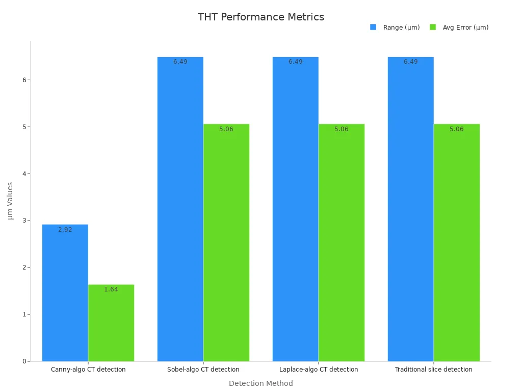
Modern THT uses non-destructive testing to check microholes. This testing gives you accurate results and saves time compared to old slice testing. You get better quality control, which means your circuit boards last longer and work better in tough conditions.
Mixed Technology
Sometimes, you need both SMT and THT on the same printed circuit board. Mixed technology lets you use the strengths of each method. You might use SMT for small, high-speed parts and THT for strong, durable connections. This approach helps you build complex products like automotive systems or industrial machines.
Industry reports show that different assembly types meet different needs. For example, multilayer and flexible printed circuit boards help you handle high-speed data or harsh environments. You can choose the right assembly type based on what your device must do and how reliable it needs to be.
Tip: When you plan your pcb assembly, think about the demands of your application. The right assembly type helps you get the best performance and reliability from your circuit boards.
Assembly Steps
Design for Assembly (DFA)
You start the pcb assembly process with Design for Assembly (DFA). This step helps you create printed circuit boards that are easy to build and less likely to have errors. You group similar components together, use clear silkscreen markings, and avoid crowding parts. You also choose standard footprints and optimize trace routing. These choices make the assembly process smoother and reduce mistakes.
Mechanical and electrical testing methods, such as Automated Optical Inspection (AOI), X-ray, and peel tests, help you find defects like cracked joints or poor soldering. These tests show that good DFA practices lower error rates and boost reliability. You can measure DFA success with metrics like First Pass Yield (FPY), defect rate, cycle time, throughput, and rework rate. High FPY and low defect rates mean your assembly is efficient and accurate.
Tip: Good DFA helps you save time and money by making sure your circuit boards are easy to assemble and less likely to fail.
Solder Paste Application
Next, you apply solder paste to the pcb. This step is critical for surface mount assembly. You use a stencil to place the right amount of solder paste on the pads where components will sit. The quality of solder paste and how you apply it affect the reliability of your circuit boards.
-
Solder alloy and flux composition impact joint strength, especially in tough environments.
-
Solder powder size and viscosity affect how well the paste prints and sticks.
-
Flux activity helps remove oxides and improves wetting.
-
No-clean flux must not leave harmful residues.
-
Up to 75% of SMT defects come from poor solder paste printing.
Solder Paste Inspection (SPI) machines check the volume, height, and area of the paste. They help you catch problems early, like too much or too little paste, which can cause solder bridges or weak joints. Controlling these factors keeps your pcb assembly process reliable.
Pick and Place
After solder paste application, you move to the pick and place step. Here, machines or skilled workers place components onto the pcb. Automated pick-and-place machines use vision systems to ensure each part lands in the right spot. This step is fast and accurate, which is important for high-volume pcb assembly.
Quality control is key. You calibrate machines and train technicians to spot and fix placement issues. Accurate placement means your circuit boards work as designed and pass later inspections.
Reflow Soldering
Once components are in place, you use reflow soldering to attach them to the pcb. The board passes through a reflow oven, where controlled heat melts the solder paste and forms strong joints. The temperature profile in the oven is critical. If the heat is too high or too low, you risk defects like solder voids or weak connections.
Studies show that the reflow profile affects both mechanical and thermal properties of the solder joints. For example, a peak temperature of 247°C for 300 seconds can ensure good reliability. Statistical models link reflow temperature to product yield and defect rates. About 30% of SMT defects can come from this step, so you must monitor and control the process closely.
Through-Hole Soldering
Some components, like connectors or large parts, need through-hole soldering. You insert these parts into holes on the pcb and solder them on the other side. For small batches or prototypes, you might use hand soldering for precision. For large runs, automated machines and wave soldering speed up the process.
Through-hole assembly gives your circuit boards extra strength and reliability. This method is common in automotive, aerospace, and industrial products. You may face challenges like tight spacing or heat-sensitive parts, but you can solve these with careful design, selective soldering, and thermal shielding.
Inspection (SPI, AOI)
Inspection is a vital part of the pcb assembly process. You use Solder Paste Inspection (SPI) to check the paste before soldering. After soldering, Automated Optical Inspection (AOI) scans the board for defects like missing parts, wrong components, or bad solder joints.
|
Metric |
Definition / Formula |
Description |
Improvement (%) |
|---|---|---|---|
|
R = TP / (TP + FN) |
Proportion of actual defective images correctly identified. |
+1.4 |
|
|
Precision (P) |
P = TP / (TP + FP) |
Proportion of identified defective images that are truly defective. |
+3.8 |
|
mean Average Precision (mAP) |
fmAP = (1/n) * Σ ∫ P(R) dR over [0,1] |
Average precision across categories at IoU threshold 0.5, measuring overall detection accuracy. |
+2.9 |
AOI systems use high-precision cameras and deep learning to spot problems quickly. These tools improve inspection accuracy, reduce labor costs, and help you maintain high standards for your circuit boards.
Testing
The final step in the pcb assembly process is testing. You want to make sure your assembled circuit boards work under real-world conditions. You use several types of tests:
-
Environmental stress tests: thermal cycling, humidity, vibration, and shock.
-
Electrical stress tests: power cycling and electrostatic discharge.
-
Specialized tests: salt spray, electromigration, surface insulation resistance, and thermal shock.
-
Highly Accelerated Life Testing (HALT): finds early failure points.
-
Functional testing: checks if the pcb works as intended.
You also use tools like X-ray imaging and scanning electron microscopy for failure analysis. These tests confirm that your circuit boards are durable and reliable.
|
Test Type |
Purpose/What it Validates |
Typical Conditions/Parameters |
Common Failure Modes/What it Reveals |
|---|---|---|---|
|
Tests PCB's ability to withstand repeated temperature changes |
Temperature range: -40°C to +125°C; 500-1000 cycles |
Solder joint cracking, delamination, barrel cracks |
|
|
Damp Heat (Humidity) |
Evaluates resistance to moisture and corrosion |
85°C, 85% RH, >1000 hours |
Moisture absorption, metal migration, solder mask blister |
|
Salt Spray |
Assesses corrosion protection in harsh environments |
Salt concentration, ~35°C, spray duration varies |
Conductor corrosion, solder joint oxidation |
|
Electromigration & SIR |
Measures long-term insulation reliability under bias |
85°C/85% RH with bias voltage |
Metal migration, short circuits (CAF growth) |
|
Vibration & Mechanical Shock |
Tests mechanical integrity under transport and operation stress |
Multi-axis vibration, high G-force impacts |
Cold solder joints, solder ball fatigue, pin breakage |
|
Thermal Shock |
Examines rapid temperature change effects |
Sudden high/low temperature shifts |
Welding interface failure, PTH coating peeling, delamination |
|
Highly Accelerated Life Test (HALT) |
Exposes early failure points under extreme conditions |
Rapid heating/cooling, vibration, voltage/current impulses |
Early potential failure detection |
|
Functional Testing |
Validates overall PCB performance under real application conditions |
Current/voltage stability, signal integrity, IO response |
Usability and stability of PCB in operation |
Testing ensures your pcb assembly meets industry standards and customer expectations. You can trust your circuit boards to perform well in any environment.
Quality Assurance
Inspection Methods
You need strong inspection methods to keep your pcb assembly reliable. Each method finds different types of problems. You can use visual inspection for a quick and cost-effective quality check. Skilled inspectors look for missing parts or obvious defects. Automated Optical Inspection (AOI) uses cameras and software to scan thousands of points on the board. This method finds small errors fast and helps you catch mistakes early in the process. X-ray inspection lets you see inside the board. You can spot hidden issues like solder bridges or misaligned parts. Electrical testing checks if your pcb works as it should. It confirms that all connections are correct.
|
Inspection Method |
Key Features |
Contribution to Quality Assurance |
|---|---|---|
|
Visual Inspection |
Quick, cost-effective, relies on expert human judgment; detects gross defects |
Initial defect detection; human insight catches subtle issues |
|
Automated Optical Inspection (AOI) |
High precision, fast, comprehensive coverage; analyzes thousands of data points rapidly |
Rapid, accurate defect detection; minimizes defects in production |
|
X-Ray Inspection |
Non-destructive, detailed internal imaging; suitable for complex/multilayer boards |
Detects hidden defects like voids, misalignment, solder bridges |
|
Electrical Testing |
Checks electrical performance of PCB |
Validates functional integrity of assembled boards |
Some companies use a dual inspection system. One inspector checks passive parts, and another checks active parts. This approach reduces mistakes and improves accuracy. Certified inspectors follow strict standards, which helps you trust the results.
IPC-A-610 Standards
You should know about IPC-A-610 standards. These rules guide you in making high-quality pcb assemblies. The standards show you what a good solder joint looks like and how to spot defects. When you follow IPC-A-610, you make sure your assembly meets global quality levels. Inspectors who hold IPC-A-610 certification know how to judge every detail. This helps you avoid costly errors and keeps your process on track.
Tip: Ask your assembly partner if their team holds IPC-A-610 certification. This shows they care about quality and follow best practices.
Ensuring Reliability
You want your pcb to last a long time and work well in tough conditions. Reinforcement methods, like bottom filling and corner fixing, make solder joints much stronger. These techniques can increase the lifetime of your assembly by up to 84 times compared to boards without reinforcement. Simulation tools help you predict where failures might happen. You can use this information to improve your design and process.
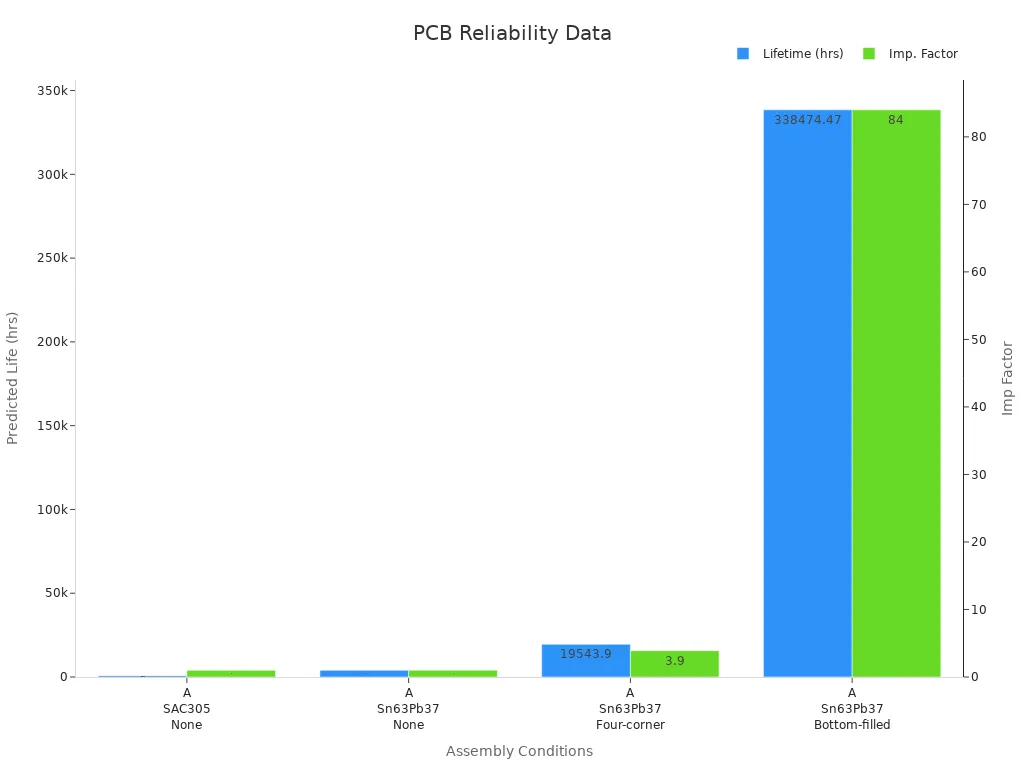
Testing and analysis show that larger pad sizes can help with vibration but may reduce life during temperature changes. You should always match your design choices to the needs of your product. Careful quality check steps, strong standards, and smart reinforcement keep your pcb assembly reliable for years.
Choosing a PCB Assembly Partner
Key Factors
When you choose a pcb assembly partner, you want to make sure they meet your needs. Look for these important factors:
-
Experience and expertise in pcb assembly for your industry
-
Use of advanced equipment like pick-and-place machines, reflow ovens, AOI, and X-ray inspection
-
Certifications such as ISO 9001 and IPC-A-610 for quality assurance
-
Strong quality control with in-house testing and inspection
-
Flexible production capacity for both prototypes and large orders
-
Engineering support for design for manufacturability and troubleshooting
-
Good reputation and positive client reviews
-
Compliance with environmental and ethical standards
These factors help you find a partner who can deliver high-quality boards on time.
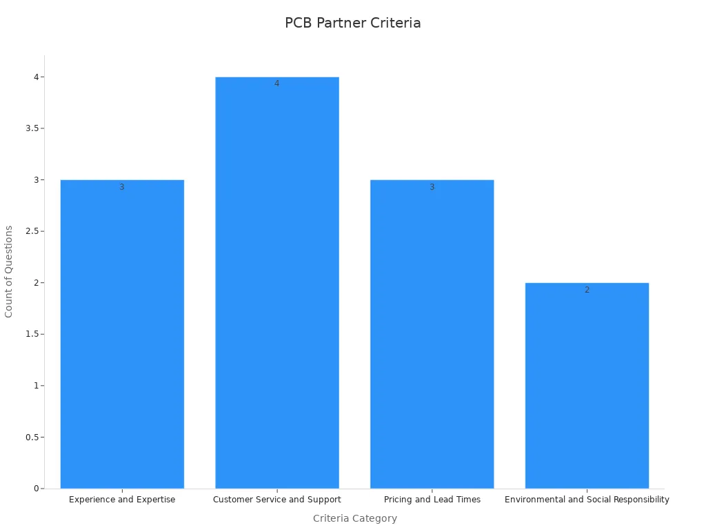
Questions to Ask
Before you decide, ask your potential pcb assembly partner some key questions. This helps you understand their strengths and how they handle projects.
|
Criteria Category |
Example Questions |
|---|---|
|
Experience and Expertise |
How long have you been in business? What industries do you serve? Can you provide references? |
|
Customer Service and Support |
What is your communication process? How do you handle support? What is your lead time? |
|
Pricing and Lead Times |
What is your pricing structure? Are there extra costs? What is your production lead time? |
|
Environmental Responsibility |
What is your environmental policy? How do you ensure compliance with regulations? |
You should also ask about their testing methods, supply chain practices, and ability to handle special requests.
Tips for Success
You can improve your chances of success by following these tips:
-
Check for certifications like ISO 9001 and IPC-A-610
-
Ask for a sample run before a full order
-
Visit the facility if possible to see their process
-
Use partners with strong supply chain management and testing protocols
-
Build a good relationship with clear communication
Good communication and fast support help solve problems quickly and keep your project on track. Customer satisfaction scores and quick response times show how well a partner supports you.
A reliable pcb assembly partner helps you avoid delays, ensures quality, and supports your business growth.
You can achieve reliable results by following each assembly step and focusing on quality checks. Pay attention to key metrics like first pass yield, defect rate, and rework rate. Use the table below to see important checkpoints that help you measure quality and process control:
|
Step / Checkpoint |
Description or Range |
|---|---|
|
Solder Paste Metal % |
|
|
Solder Paste Adhesion |
200 Pa.s to 800 Pa.s |
|
Final Inspection |
Functional test of electrical signals |
|
Defect Types |
Open, short, abrasion, tracking defects |
|
Inspection Methods |
Visual, AOI, X-ray, Functional, In-Circuit Testing |
|
Quality Standards |
IPC-A-610, ISO 9001, RoHS, UL |
Choose your assembly partner carefully. Review their certifications and testing methods. If you want to learn more, explore guides on design, inspection, and testing for pcb projects.
FAQ
What is the difference between SMT and THT assembly?
SMT places components on the surface of the board. THT puts component leads through holes in the board. You use SMT for small, lightweight parts. You use THT for strong, durable connections.
How do you check the quality of a PCB assembly?
You use inspection methods like AOI, X-ray, and electrical testing. These tools help you find missing parts, bad solder joints, or hidden defects. You can trust these checks to keep your boards reliable.
Can you assemble both small and large batches?
Yes, you can assemble both. Automated machines work well for large batches. Skilled workers handle small runs or prototypes. You get flexibility for any project size.
What should you provide to start PCB assembly?
You need to give a bill of materials (BOM), Gerber files, and assembly drawings. These documents help the assembly team place the right parts in the right spots.
How long does PCB assembly usually take?
Assembly time depends on your order size and complexity. Simple boards may take a few days. Complex or large orders can take one to two weeks. Ask your partner for a clear timeline.