

Op Amp Integrator Circuits and how they transform input signals
When you use op amp integrator circuits, you turn an input signal into a new output that represents the time integral of the input voltage. Imagine you draw a line under a curve—this area shows how the signal builds up over time.
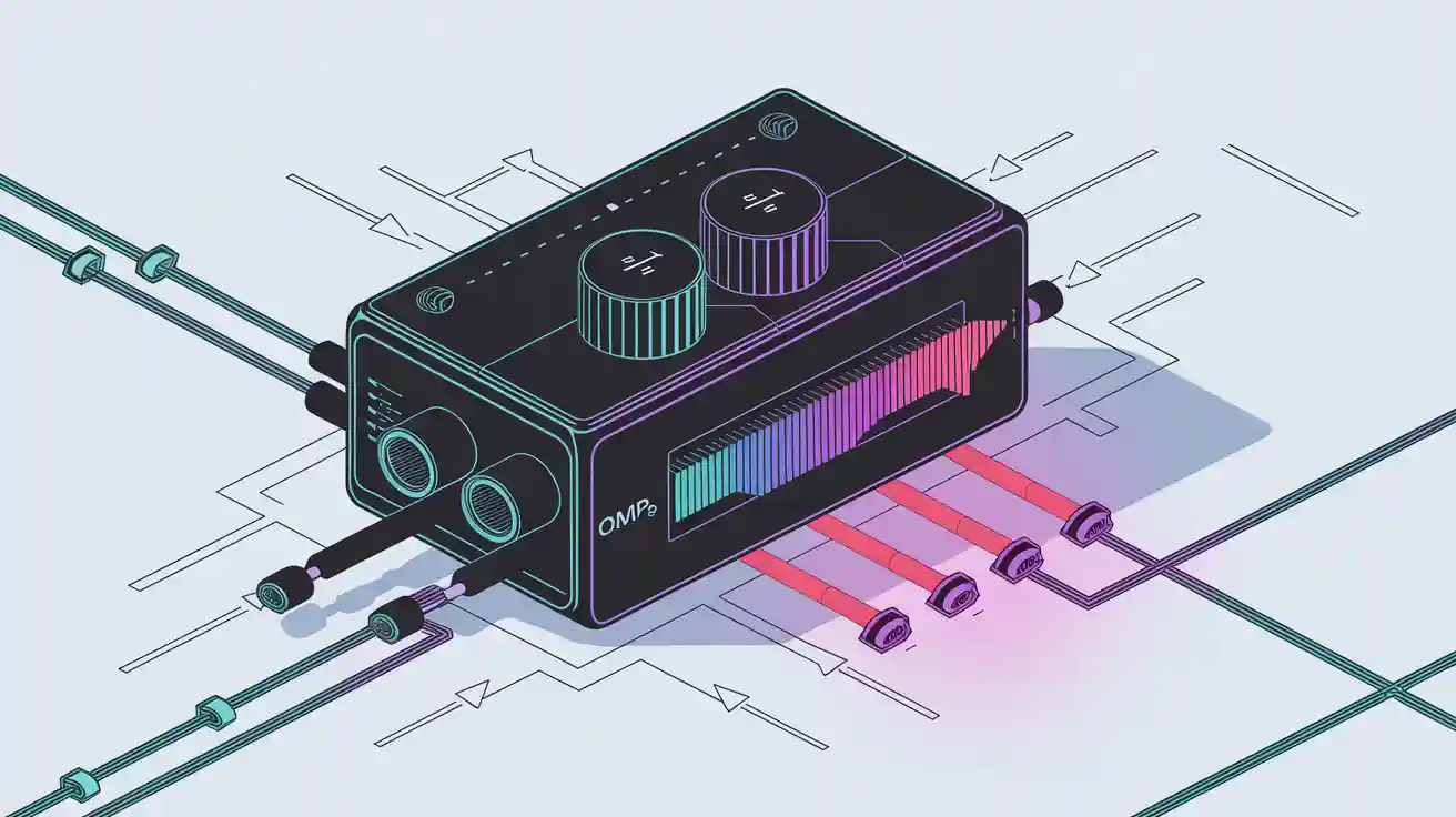
When you use op amp integrator circuits, you turn an input signal into a new output that represents the time integral of the input voltage. Imagine you draw a line under a curve—this area shows how the signal builds up over time. For example, if you send a 1 V peak sine wave at 5 kHz as your input signal, the output becomes a 0.318 V peak cosine wave, showing the integration in action. If you use a square wave input voltage, the output voltage rises or falls in a straight line, creating a triangle shape. This transformation helps you process signals in audio, sensor, or control circuits.
Key Takeaways
-
Op-amp integrator circuits turn input signals into output voltages that represent the total area under the input over time, creating new waveforms like ramps and triangles.
-
The circuit inverts the input signal, causing a 180-degree phase shift, which is important for designing signals that need to be out of phase.
-
Choosing stable components like film or ceramic capacitors and low-noise op-amps helps keep the output accurate and reduces drift and noise.
-
You can control how fast the output changes by adjusting the resistor and capacitor values, which set the circuit’s time constant.
-
Op-amp integrators are useful in many applications, including signal processing and waveform generation, making them valuable tools for audio, sensor, and control circuits.
Op Amp Integrator Circuits Overview
Core Function and Operation
You use op-amp integrator circuits to perform mathematical integration on input signals. This means the output voltage shows the total area under the input voltage curve over time. In practical terms, you can turn a changing input signal into a new output that builds up or decreases smoothly.
-
Op-amp integrator circuits use a resistor and a capacitor to set how fast the output changes. The resistor connects to the input, and the capacitor sits in the feedback path.
-
The output voltage follows the formula:
Vout = -1/(R × C) × ∫Vin dt
This formula means the output depends on the size of the resistor (R), the capacitor (C), and the input voltage over time. -
You often see op-amp integrator circuits in devices like analog-to-digital converters, waveform generators, and analog computers.
-
To keep the circuit stable, you might add a large resistor in parallel with the feedback capacitor. This helps prevent the output from drifting or saturating when the input signal has a DC component.
-
Choosing the right components matters. Use resistors with tight tolerance and capacitors that do not change much with temperature. Pick op-amps with low noise and high gain for the best results.
Here is a table showing how different resistor and capacitor values affect the circuit:
|
Example |
Resistor (R) |
Capacitor (C) |
Time Constant (τ) |
Input Voltage Range |
Output Voltage Range |
Frequency Response Roll-off |
|---|---|---|---|---|---|---|
|
1 |
10 kΩ |
0.1 μF |
±5 V |
±0.5 V |
-20 dB/decade |
|
|
2 |
100 kΩ |
0.01 μF |
1 ms |
±0.5 V |
±0.05 V |
-20 dB/decade |
|
3 |
1 kΩ |
1 μF |
1 ms |
±50 V |
±5 V |
-20 dB/decade |
Inverting Nature and Phase Shift
When you build an op-amp integrator, you use the inverting input of the op-amp. This setup causes the output to flip the input signal upside down. In other words, the output has a 180-degree phase shift compared to the input.
-
The inverting input uses negative feedback, which keeps the voltage at the input close to zero. This is called a "virtual earth."
-
The output voltage always moves in the opposite direction of the input. If the input goes up, the output goes down, and vice versa.
-
The formula for the output includes a negative sign, showing this inversion.
-
Even though you replace the feedback resistor with a capacitor in an op-amp integrator circuit, the inverting nature and phase shift stay the same.
-
This phase shift is important for signal processing. For example, if you put in a sine wave, the output becomes a cosine wave, which is shifted by 180 degrees.
Tip: Always remember that the output of an op-amp integrator circuit will be inverted. This phase shift can help you design circuits that need signals out of phase with each other.
Op-Amp Integrator Circuit Structure
Schematic and Key Components
When you build an op-amp integrator, you start with a simple schematic. The op-amp integrator circuit uses a resistor at the input and a capacitor in the feedback path. You connect the input voltage to the resistor, which then goes to the inverting input of the op-amp. The capacitor connects from the output back to the inverting input. The non-inverting input usually connects to ground.
The op-amp integrator circuit works because the op-amp uses negative feedback. This feedback keeps the inverting input at a virtual ground. The resistor and capacitor together form an RC network. This network controls how the circuit responds to changes in the input voltage.
You can add a resistor in parallel with the feedback capacitor. This resistor helps control drift and keeps the output from saturating when the input voltage has a DC offset.
Here is a quick look at the main parts you need for an op-amp integrator circuit:
-
Operational amplifier: This device amplifies the difference between its two inputs.
-
Input resistor: This resistor sets the current that flows into the circuit from the input voltage.
-
Feedback capacitor: This capacitor stores and releases charge, allowing the circuit to perform integration.
-
Compensating resistor (optional): This resistor, placed in parallel with the capacitor, helps with stability.
You can test the op-amp integrator by applying a step input voltage and watching the output ramp up or down. If you use a square wave as the input voltage, the output becomes a triangle wave. Changing the resistor or capacitor values changes how fast the output ramps.
Role of the Capacitor
The capacitor is the heart of the op-amp integrator. When you apply an input voltage, the capacitor starts to charge. At first, it acts almost like a short circuit, letting current flow easily. As it charges, its impedance increases, and the output voltage ramps up or down, depending on the direction of the input voltage.
The rate at which the output changes depends on the RC time constant. This time constant comes from the values of the input resistor and the feedback capacitor. If you use a larger capacitor or resistor, the output changes more slowly. If you use smaller values, the output changes faster.
Different types of capacitors affect the performance of your op-amp integrator circuit. Ceramic capacitors work well for stability and frequency response. Film capacitors have low loss and stable frequency characteristics. Electrolytic capacitors need careful handling because they can age and are sensitive to temperature and polarity. You should choose a capacitor that matches your needs for stability and accuracy.
|
Capacitor Type |
Key Features |
Use in Integrator Circuit |
|---|---|---|
|
Ceramic |
Stable, good for frequency response |
Good for most op-amp integrator circuits |
|
Film |
Low loss, stable frequency |
Great for precision integrator circuits |
|
Electrolytic |
Sensitive to polarity and temperature, ages |
Use with caution in integrator circuits |
|
Trimmer/Variable |
Adjustable, larger size |
Fine-tuning integrator circuit |
Tip: Always check the temperature range and stability of your capacitor. This helps your op-amp integrator circuit work reliably over time.
Input Signal Transformation
Step, Square, and Sine Inputs
When you connect different types of input signals to an op-amp integrator, you see unique changes in the output voltage. The op-amp integrator takes the input voltage and creates an output voltage waveform that is the time integral of the input. This means the output signal shape depends on the type of input signal you use.
You can test the op-amp integrator with three common types of input signals:
-
Step Signal: This signal jumps from zero to a fixed value and stays there. When you apply a step input voltage to the op-amp integrator, the output voltage ramps down in a straight line. The ramp's slope depends on the step size and the RC time constant. The output moves in the opposite direction because the op-amp integrator inverts the signal.
-
Square Wave: This signal switches between two levels, creating sharp transitions. If you use a square wave as the input voltage, the op-amp integrator produces a triangular output voltage. Each time the square wave changes, the output voltage ramps up or down, forming a triangle shape.
-
Sine Wave: This signal rises and falls smoothly. When you feed a sine wave into the op-amp integrator, the output voltage becomes a cosine wave. The output signal shifts by 180 degrees, showing the phase shift caused by the inverting nature of the circuit.
You can see these transformations in the table below:
|
Input Signal |
Output Signal |
Explanation |
|---|---|---|
|
Step Signal |
For a positive step input, the output is a negative ramp due to the inverting nature of the integrator. The slope is proportional to -A/RC, where A is the step amplitude and RC is the integrator time constant. |
|
|
Square Wave |
Triangular Wave |
The square wave can be seen as alternating positive and negative step inputs. Each step produces a ramp output, resulting in a triangular waveform output. |
|
Sine Wave |
Cosine Wave |
A sine wave input results in a cosine wave output, demonstrating the integral relationship between input and output signals in the op-amp integrator. |
Note: The RC time constant controls how quickly the output voltage changes. You can adjust the resistor or capacitor to change the speed of the output signal.
Output Waveform Examples
You can observe the transformation of the input voltage waveform by looking at the output voltage on an oscilloscope. The op-amp integrator always inverts the signal, so the output voltage waveform is flipped compared to the input.
-
Square to Triangle: When you use a square wave as the input signal, the op-amp integrator creates a triangle wave at the output. The square wave acts like a series of step inputs. Each time the input voltage jumps, the output voltage ramps up or down. The result is a smooth triangle shape. Simulation results and lab measurements confirm this transformation. You can see the triangle wave's frequency matches the square wave's frequency, but the shape is different.
-
Step to Ramp: If you apply a step input voltage, the output voltage ramps in the opposite direction. The ramp continues as long as the step stays high. The slope of the ramp depends on the input voltage and the RC time constant. This behavior matches what you see in measured data.
-
Sine to Cosine: When you use a sine wave as the input signal, the op-amp integrator produces a cosine wave at the output. The output voltage waveform shifts by 180 degrees, showing the phase shift. This phase shift means the output voltage reaches its peak when the input voltage crosses zero. Experimental results show this phase shift and confirm the mathematical relationship between the input and output.
You might wonder if you can turn a triangle wave into a sine wave using an op-amp integrator. In practice, integrating a triangle wave does not create a perfect sine wave. The triangle wave has sharp corners, so the output voltage does not become smooth like a sine wave. To get a sine wave from a triangle wave, you need extra filtering, such as a low-pass filter or another integrator stage.
Tip: Always remember that the op-amp integrator inverts the output signal. This 180-degree phase shift is a key feature of the circuit. You can use this property to create signals that are out of phase with your input.
You can use the op-amp integrator to process many types of input signals. The circuit helps you create new output voltage waveforms for audio, sensor, and control applications. By understanding how the op-amp integrator transforms each input signal, you can design better analog circuits.
Frequency Response and Limitations
Frequency Behavior
You need to understand how the response of the integrator changes with frequency. At low frequencies, the output voltage increases steadily as the circuit integrates the input. As you raise the frequency, the output voltage does not keep up as well. The gain of the circuit drops by about -20 dB for every tenfold increase in frequency. This roll-off means the circuit acts like a lowpass filter.
You can see how different parameters affect the frequency response in the table below:
|
Parameter |
Value/Description |
|---|---|
|
Frequency response shape |
Flat at DC, rolls off with frequency |
|
Roll-off rate |
-20 dB/decade over defined frequency range |
|
Example component values |
R1 = R2 = 1 kΩ, C = 1 μF |
|
-3 dB frequency |
1/(2πR2C) = 160 Hz |
|
Useful frequency range |
100 Hz to 250 kHz |
The output voltage formula for an ideal integrator is Vout = -1/(RC) × ∫Vin dt. In real circuits, you often add a resistor in parallel with the feedback capacitor. This resistor limits the gain at low frequencies and keeps the output voltage from drifting or saturating. You can also add a resistor in series with the capacitor to improve high-frequency performance. The integration time constant (RC) sets how quickly the output voltage changes.
-
The corner frequency marks the point where the circuit stops acting like a perfect integrator.
-
The gain-bandwidth product of the op-amp, such as 1.2 MHz for the LM324, limits the highest frequency you can use.
-
Frequency response measurements show that the output voltage drops off as you move past the useful frequency range.
Non-Ideal Effects
Real op-amp integrator circuits do not behave perfectly. Several factors can affect the output voltage and limit the accuracy of your circuit.
-
Input bias current and input offset voltage can cause the output voltage to drift over time.
-
The gain-bandwidth product of the op-amp limits how fast the output voltage can change at high frequencies.
-
If you use large resistor or capacitor values, you might see more noise in the output voltage.
-
Adding a feedback resistor helps prevent the output voltage from saturating when the input has a DC offset.
You should always check the specifications of your op-amp. For example, the LM324 has a typical input bias current of 45 nA and an input offset voltage of 2 mV. These values can shift the output voltage even if the input is zero. The DC gain of the circuit, set by the resistor values, also affects how much the output voltage can change for a given input.
Tip: Always test your circuit with different input signals and frequencies. This helps you see how the output voltage responds in real-world conditions.
Integrator Amplifier Design Tips
Stability and Drift Reduction
When you build an integrator amplifier, you want the output to stay steady and not drift over time. Drift can make your integrator circuit less accurate. You can reduce drift by adding a resistor in parallel with the feedback capacitor. This resistor helps control the output when the input has a small DC offset. If you skip this step, the output might slowly move toward the supply rails and stop working as expected.
You should also use an op-amp with low input offset voltage and low bias current. These features help keep the output from drifting. If you notice noise or unwanted changes in the output, try using shielded cables and keep your wires short. Good layout and grounding in your circuit design will also help reduce drift and noise.
Tip: Always test your integrator amplifier with different input signals. This helps you spot drift or instability early.
Component Selection
Choosing the right parts for your integrator amplifier makes a big difference. Start by picking resistors and capacitors with tight tolerances. This means their values stay close to what you expect. Stable capacitors, like film or ceramic types, work best in an integrator circuit. Avoid electrolytic capacitors unless you have no other choice.
You can use online tools to help with part selection. For example, National Semiconductor's 'Amplifiers Made Simple' tool lets you compare op-amps for your integrator amplifier. This tool uses real manufacturer data and simulation models. You can see how different parts perform in your integrator circuit before you build it. The tool even gives you a bill of materials and lets you change values to fit your needs. This approach helps you make smart choices based on real-world performance.
|
Component |
What to Look For |
Why It Matters |
|---|---|---|
|
Op-Amp |
Low offset, low bias current |
Reduces drift and noise |
|
Resistor |
Tight tolerance (1% or better) |
Keeps output accurate |
|
Capacitor |
Stable type (film, ceramic) |
Maintains integration quality |
Note: Always check the datasheet for each part. This helps you avoid surprises in your integrator amplifier.
Applications of Op-Amp Integrator
Analog Signal Processing
You often use op-amp integrators in signal processing systems. These circuits help you change the shape of signals in many useful ways. For example, you can smooth out noisy signals or create new waveforms for further analysis. The integrator takes an input voltage and produces an output that shows the total effect of the input over time. This process is called integration, and it is a key part of analog signal processing.
Here is a table that shows how different input signals behave in a signal processing system with an op-amp integrator:
|
Input Signal Type |
Output Waveform Description |
Key Technical Details |
|---|---|---|
|
Step Signal |
Negative ramp signal; slope depends on input size. Output saturates after some time. |
Shows time integration and ramp output. |
|
Square Wave |
Triangular waveform. |
Integration of periodic signals creates triangle waves. |
|
Sine Wave |
Cosine waveform, phase-shifted and scaled. |
Demonstrates phase shift and amplitude scaling. |
|
Frequency Response |
Gain drops as frequency rises; acts like a low-pass filter. |
Gain falls at -20dB/decade; practical limits exist. |
|
Practical Use |
Real circuits need changes to avoid errors. |
Modifications help with offset and bandwidth issues. |
You see op-amp integrators in audio filters, sensor circuits, and control systems. In each case, the integrator helps you process signals in a way that makes them easier to use or measure. The basic math behind the integrator, V0 = -1/RC ∫Vt dt, shows why it is so important in signal processing.
Note: You can improve your signal processing results by choosing the right resistor and capacitor values for your integrator circuit.
Waveform Generation
You can also use op-amp integrators to create new waveforms for testing and measurement. If you connect a square wave generator to an op-amp integrator, you get a triangular wave at the output. This setup works because the integrator changes the sharp steps of the square wave into smooth ramps. Many labs and classrooms use this method to show how integration works in real circuits.
You might build a simple signal generator by combining a square wave oscillator and an op-amp integrator. This combination lets you produce both square and triangle waves, which are useful for signal processing experiments. Measurement data from real circuits show that the output matches what you expect: a clean triangle wave follows the square wave input. This result proves that op-amp integrators work well for waveform generation.
Tip: Try using an op-amp integrator in your own signal processing projects. You will see how easy it is to create and shape signals for different uses.
You have seen how op-amp integrator circuits change input signals by creating an output voltage that shows the time integral. When you use different signals, the output voltage takes on new shapes, like ramps or triangle waves. The phase shift always flips the output voltage compared to the input. Careful design helps you keep the output voltage accurate. Try using different input signals and watch how the output voltage responds in your own projects. This hands-on approach helps you understand the real power of integration.
FAQ
What happens if you use a DC input with an op-amp integrator?
If you use a DC input, the output voltage ramps up or down without stopping. The output can quickly reach the supply limit. You should add a resistor in parallel with the feedback capacitor to prevent this drift.
Why does the output signal invert in an op-amp integrator?
The circuit uses the inverting input of the op-amp. This setup flips the output signal. If your input goes positive, the output goes negative. This 180-degree phase shift is a key feature of integrator circuits.
Can you use any type of capacitor in an integrator circuit?
You should choose stable capacitors like ceramic or film types. These keep your circuit accurate. Electrolytic capacitors can drift or change value over time. They may cause errors in your output signal.
How do you adjust the speed of integration?
-
Increase the resistor or capacitor value to slow down the output change.
-
Decrease either value to make the output ramp faster.
-
The RC time constant controls how quickly the output responds to the input.


