Integrated Circuits: Technical Specifications and Industry Standards
Technical specifications and industry standards are very important in making and choosing integrated circuits. These specifications show how an integrated circuit works in different situations.

Technical specifications and industry standards are very important in making and choosing integrated circuits. These specifications show how an integrated circuit works in different situations. They also help find problems that might make the circuit less reliable. Industry standards are made by groups like IEC and JEDEC. These standards make rules for quality and following the law. This helps companies make good integrated circuits. Datasheets and careful testing also help. They give clear instructions and help find problems early. This makes products more reliable and helps people trust them.
Key Takeaways
-
Technical specifications and datasheets help engineers pick the right integrated circuits. They also help design circuits that work well in many situations.
-
Industry standards from groups like IEC, JEDEC, and IEEE make sure devices are safe and work together. These rules help keep quality high all over the world.
-
Testing methods and reliability checks find problems early. They also make sure integrated circuits last a long time and stay safe.
-
Manufacturers use strict steps and write down every part of the process. This helps them make good chips that follow laws and safety rules.
-
Picking between standard ICs and ASICs depends on how hard the job is. It also depends on how well it needs to work and how much risk is okay. This helps each project get the best choice.
Integrated Circuits: Specifications
Electrical Parameters
Engineers use electrical parameters to show how well integrated circuits work. These details help decide if a semiconductor device fits a certain job. The most common ones are supply voltage, input and output voltage levels, current use, and power dissipation. Each one changes how the integrated circuit works with other parts in a system.
-
Supply Voltage (Vcc or Vdd): This number tells the working range for the integrated circuit. Designers need to match the supply voltage to what the chip needs.
-
Input and Output Voltage Levels: These numbers set the logic points for digital semiconductor devices. They make sure different chips on the same board can work together.
-
Current Consumption: This shows how much current the integrated circuit uses when it runs. Using less current means less heat and longer battery life.
-
Power Dissipation: Power dissipation tells how much energy the integrated circuit turns into heat. Designers use this to pick the right way to cool the chip.
Performance rules for electrical parameters are often in datasheets. These rules help engineers check if the integrated circuit will do its job. Checking these numbers makes sure the chip works in normal and tough situations. Good checking helps make dependable integrated circuits.
Thermal and Reliability
Thermal management and reliability are very important in designing integrated circuits. Semiconductor devices make heat when they work. If the temperature gets too high, the chip may not work well or last long. Engineers use different ways to measure and control heat.
-
Thermal Resistance (θJA): This shows the temperature change between the chip and the air for each unit of power. Lower thermal resistance means the chip loses heat better.
-
Junction Temperature (TJ): This is the real temperature inside the integrated circuit. Keeping TJ safe is needed for the chip to last a long time.
-
Transient Thermal Characteristics: Engineers use RC circuits to model how the temperature of a silicon based integrated circuit changes over time. These models help guess how long a chip can run at a certain power before it gets too hot.
Reliability numbers help makers and users know how long a semiconductor device will work. Important numbers are:
-
Failure Rate: This is the percent of devices that fail out of all tested.
-
FITS (Failures In Time): This counts failures for every billion device hours.
-
DPM (Defects Per Million): This shows how many bad chips are made for every million.
-
Confidence Intervals: These are found using math to guess the real failure rate.
Makers use many tests to check if integrated circuits are reliable:
-
High Temperature Operating Life (HTOL): This test acts like long use at high temperature and voltage.
-
Infant Life Test: This test looks for early failures.
-
Preconditioning (Precon): This test copies real-world assembly stress.
-
Biased Highly Accelerated Stress Test (HAST): This test checks if the chip can handle high temperature and humidity.
-
Temperature Humidity Bias (THB): This test checks how the chip works with heat, humidity, and electrical stress.
-
Temperature Cycle (TC): This test checks if the package can handle heating and cooling over and over.
-
Unbiased Highly Accelerated Stress Test (UHAST): This is like HAST but without electrical bias.
-
High Temperature Storage Life (HTSL): This test checks what happens if the chip is stored at high temperature for a long time.
-
Electrostatic Discharge (ESD) Tests: These include Human Body Model (HBM) and Charged Device Model (CDM).
-
Latch-Up Testing: This test checks for unwanted current paths that can hurt the chip.
Note: These tests follow rules from groups like JEDEC and AEC-Q100. They make sure integrated circuits meet tough performance and reliability rules for their whole life.
Engineers use mission profiles to show what stresses a chip will face in real use. They use models like the Arrhenius acceleration model to connect test results to real life. This helps guess how long a semiconductor device will last when used. Looking at failure rates and wear-out times, often shown as a bathtub curve, helps check the quality and reliability of every integrated circuit.
Datasheets
Datasheets are the main place to find technical information for integrated circuits. Each datasheet gives detailed specifications, performance rules, and checking steps. Engineers use these papers to compare different semiconductor devices and pick the best one for their design.
A normal datasheet has:
-
Absolute maximum ratings
-
Recommended operating conditions
-
Electrical characteristics
-
Timing diagrams
-
Pin configurations
-
Package information
The datasheet also explains how to check each parameter. This helps engineers make sure the integrated circuit will work as needed in their project. For asic and standard products, datasheets tell about special features and limits of each device. Checking datasheet values makes sure the chip design will work as planned and be good quality.
Tip: Always look at the datasheet before finishing a chip design. Careful checking of specifications can stop costly mistakes and make the finished product better.
Datasheets help pick asic and standard integrated circuits by giving clear, trusted data. They help engineers get the right function, performance, and reliability in every project. By following datasheet advice, teams can make high-quality, dependable integrated circuits that meet industry standards.
Industry Standards
IEC, JEDEC, IEEE
Some groups make the rules for integrated circuit design and testing. These groups help companies make sure every semiconductor is high quality and works well.
-
IEC (International Electrotechnical Commission) makes worldwide rules for electrical and electronic things. Their rules talk about safety, testing, and how semiconductors affect the environment. IEC standards help integrated circuits work safely in many places.
-
JEDEC (Joint Electron Device Engineering Council) makes rules for the semiconductor industry. JEDEC focuses on memory, logic, and power devices. Their rules talk about electrical limits, heat, and reliability tests. Companies use JEDEC rules to make sure integrated circuits work well and are good quality.
-
IEEE (Institute of Electrical and Electronics Engineers) makes technical rules for electronics and engineering. IEEE rules help integrated circuits talk to each other and work in systems. Many digital and analog semiconductors follow IEEE rules for sending data and using power.
These groups help companies follow industry rules. Their work helps with world trade, product safety, and making sure all integrated circuits work the same.
Automotive and Safety (AEC-Q, IEC 61508, ISO 26262)
Cars and safety systems need integrated circuits that are very reliable and safe. Special rules help with the risks and needs in these areas.
-
AEC-Q100 is a rule for car integrated circuits. It needs stress tests at different temperatures. This helps lower design risks and makes products better. Companies must show their semiconductors can handle tough car conditions.
-
IEC 61508 gives rules for safety in electronic systems. It covers the whole life of a semiconductor, from design to end. IEC 61508 needs hazard checks, safety goals, and careful testing. Companies must write down every step to show they follow the rules.
-
ISO 26262 builds on IEC 61508 for car safety. It uses ASILs to measure risk. ISO 26262 needs strong safety plans, fault checks, and testing. Companies must use special tests and checks to meet these rules.
Car rules change how engineers design and test integrated circuits. They need early safety checks, careful fault checks, and strong safety steps. Following the rules means keeping good records and showing every step is safe. These rules are now used by many companies. They help make car semiconductors more reliable and better.
Following car and safety rules keeps people and things safe. It also helps people trust the quality and safety of every integrated circuit in cars and safety systems.
Military and Aerospace (MIL-PRF-38535)
Military and space systems need integrated circuits that can survive very hard conditions. The MIL-PRF-38535 rule sets tough requirements for these places.
-
MIL-PRF-38535 covers design, testing, and quality for military semiconductors. It needs companies to use controlled steps and track all materials. Every integrated circuit must pass hard electrical and environmental tests.
-
The rule needs high reliability and long life. Companies must show their products can handle shaking, radiation, and big temperature changes. MIL-PRF-38535 also needs good records and tracking for every device.
|
Standard |
Application Area |
Key Focus |
Reliability Measures |
|---|---|---|---|
|
AEC-Q100 |
Automotive |
Stress Testing, Quality |
Temperature Grades, DPM |
|
IEC 61508 |
Functional Safety |
Lifecycle, Hazard Analysis |
Verification, Documentation |
|
ISO 26262 |
Automotive Safety |
ASILs, Safety Management |
Fault Injection, Traceability |
|
MIL-PRF-38535 |
Military/Aerospace |
Extreme Environments |
Vibration, Radiation, QA |
Military and space rules make sure integrated circuits work well in the hardest places. These rules protect important missions and help keep countries safe.
Companies that follow these rules show they care about quality and safety. Meeting these rules helps them earn trust from car, safety, military, and space customers. Following industry rules also lowers risk and helps products succeed for a long time.
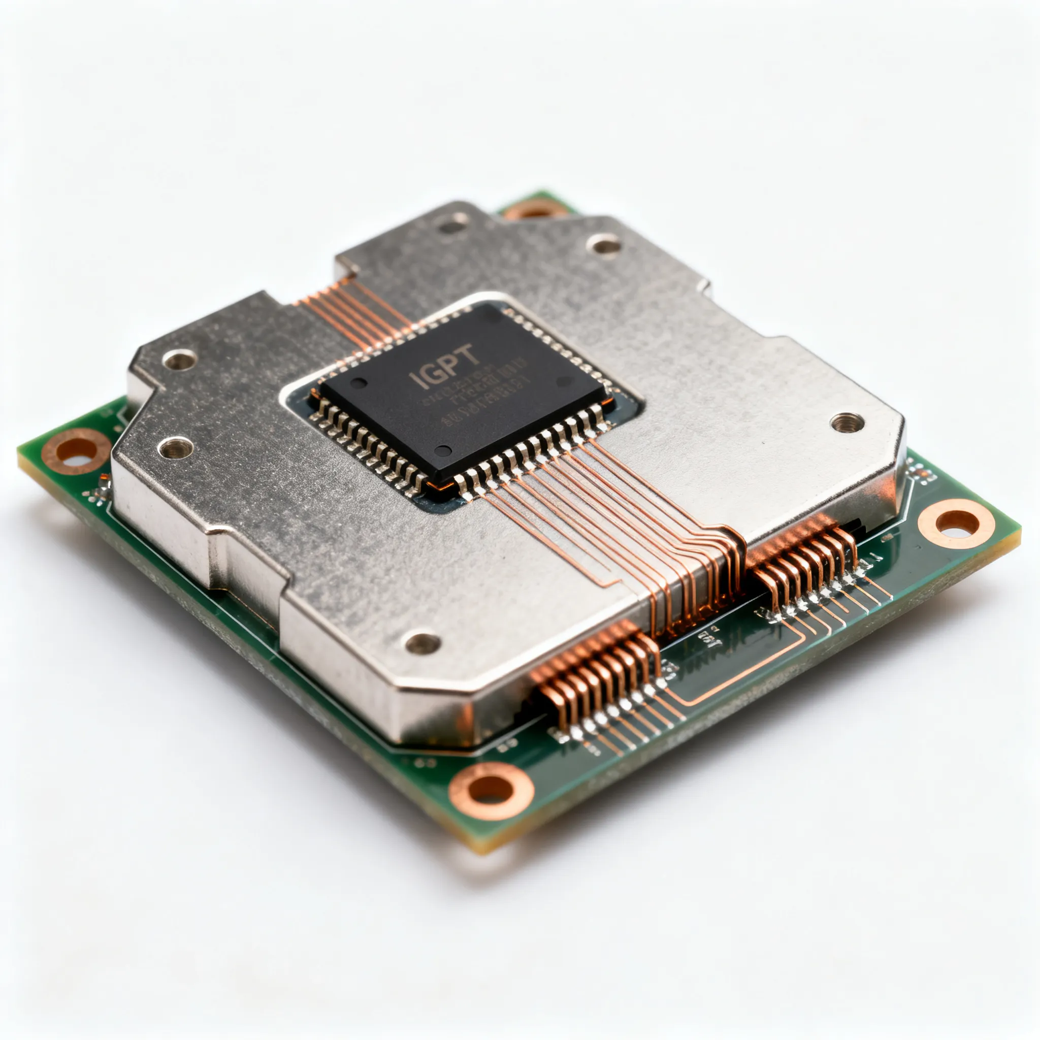
Integrated Circuit Manufacturing

Design and Fabrication
The ic manufacturing process starts with design. Engineers make careful plans for each semiconductor device. They use special tools to draw circuits and check every part. These checks make sure the design is correct before making the chip. During fabrication, workers build the semiconductor on silicon wafers. Each step uses high-tech machines to add or take away materials. The steps include photolithography, doping, etching, and deposition. At every stage, checks are done to find mistakes early.
|
Aspect |
Evidence / Finding |
|---|---|
|
Manufacturing cost |
It costs about $1.00-$5.00 per cm² to make chips. New 3D NAND technology costs around $4/cm². |
|
Energy demand |
Making chips uses 9 to 38 MJ/cm² of energy. About 75% comes from energy used at the factory. |
|
Technology node impact |
Smaller IC technology nodes use more energy and cost more. For example, going from 110 nm to 14 nm more than doubles energy use. |
|
Packaging impact |
Advanced IC packaging is about 40% of the total cost. It also uses more energy. |
|
Life cycle energy footprint |
Most energy in DRAM life cycle is used during manufacturing. This is twice as much as the energy used when running the chip. |
|
Predictive tools |
The 'GreenChip' tool shows energy use doubles from 130 nm to 7 nm nodes. It looks at IC details but not all materials or packaging. |
|
Economic analysis |
Cost-of-ownership (COO) models look at direct and indirect costs. They often do not count material costs. |
|
Environmental impact |
Making ICs adds a lot to the carbon footprint of ICT devices. Life cycle studies show this changes by device and how it is made. |
This table shows how design and making chips change cost, energy, and the environment. Checking at each step helps make chips better and more efficient.
Testing and Packaging
Testing makes sure every semiconductor meets tough rules. Engineers use many ways to check for problems in chip design and making. They run fast stress tests like Highly Accelerated Stress Test (HAST) and Temperature Cycling (TC) to find what can go wrong. Nondestructive tests help find cracks in solder joints early. New testing methods, like SJ BIST™, find hard-to-see problems in solder joints and help keep FPGA boards healthy.
-
Engineers use math models to tell different failure types apart.
-
Special algorithms help find what causes failures.
-
Probing many pins in Ball Grid Array (BGA) packages helps watch for damage over time.
-
Normal tests may miss tricky problems, so better tests are needed.
-
Looking at failure data helps make reliability predictions better.
Packaging keeps the semiconductor safe and lets it connect to other devices. Fancy packaging can be up to 40% of the total cost. Checks during packaging look for problems that could cause early failures. Testing and packaging together make sure the chip works well and lasts long.
Topographies and IP
Topographies show the 3D shape of an integrated circuit. Each semiconductor has its own special design. This design is important intellectual property. Many countries let companies register their topographies for up to 10 years. This gives them special rights to their chip designs. Protecting topographies helps companies keep their ideas safe. Checks make sure no one copies or uses the design without permission. Protecting these designs helps companies create new things and rewards their hard work.
Companies that focus on design, checking, and protecting topographies lead in making new semiconductors. Their work in making and testing chips sets the rules for quality and reliability.
Standard ICs vs. ASICs

Applications
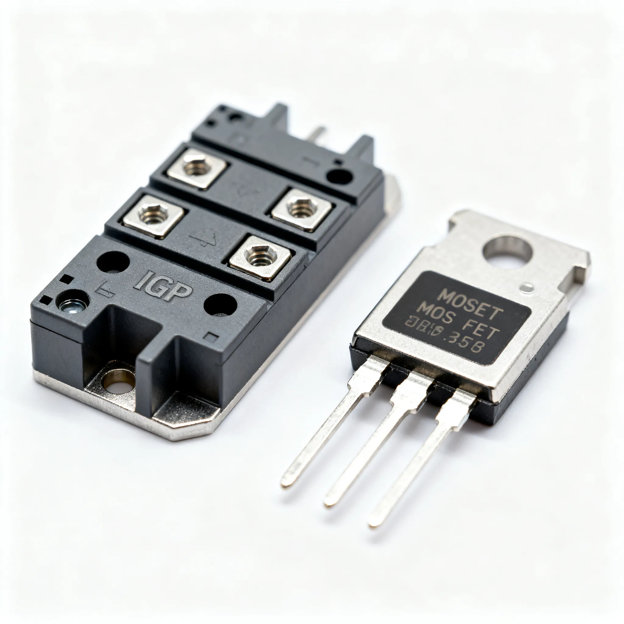
Engineers use standard integrated circuit devices for many common jobs. These chips help with things like signal processing and power management. They also do basic logic work. Making standard IC devices must follow strict industry rules. JEDEC standards make sure these chips are high quality and reliable. You can find these chips in things like TVs, factory machines, and phones.
An application specific integrated circuit, or ASIC, is made for a special job. ASIC chips are used in things like artificial intelligence and fast networks. An application specific integrated circuit is very fast and saves energy for its job. Designers pick an ASIC chip when they need something special that a standard integrated circuit cannot do.
The table below shows how both types compare:
|
Performance Metric/Test |
Description |
|---|---|
|
JEDEC Standards |
Same rules for quality and performance of standard ICs. |
|
Early Failure Rate (EFR) |
Shows how many chips fail in the first year. |
|
High Temperature Operating Life (HTOL) |
Tests how long a chip lasts under stress. |
|
High-Temperature Reverse Bias (HTRB) |
Checks if a chip stays stable when hot and under high bias. |
For ASICs, designers care about transistor density, clock speed, and cache memory. These things help an application specific integrated circuit work faster and with less delay. In AI, people check how fast, how much power, and how quickly the chip works. ASIC chips usually do better than standard integrated circuit devices for these special jobs.
Selection Criteria
Choosing between a standard integrated circuit and an application specific integrated circuit depends on a few things. Engineers use steps to help them pick the best one:
-
They decide if the device is simple or complex by looking at how it is made and tested. Simple devices are easy to check, but complex ones need more work.
-
Higher development assurance levels mean more checks are needed.
-
For standard integrated circuit devices, engineers use a process to pick, test, and get datasheets and manuals.
-
They check if standard integrated circuit devices are mature and reliable, especially if used in new ways.
-
For custom devices like an application specific integrated circuit, engineers follow a special process. Complex ASICs need more design and testing.
-
A custom device is simple only if tests can check everything.
-
Engineers look at the papers and data for standard integrated circuit intellectual property. They check what has been tested, any known problems, and service records.
-
If some data is missing, they plan extra steps to lower risk.
Tip: Good design and testing help both standard integrated circuit and application specific integrated circuit devices meet their goals.
Engineers think about how hard it is to make, how good the papers are, and how to manage risk. They pick a standard integrated circuit for normal jobs. They pick an application specific integrated circuit for special, high-speed jobs. Picking the right chip helps the system work well and last a long time.
Compliance and Performance
Manufacturer Best Practices
Manufacturers are very important for making sure semiconductors work well and follow the rules. They use strict steps when making chips and write down everything they do. Good Manufacturing Practice (GMP) and Good Documentation Practice (GDP) help them do this. These practices help control how chips are made and keep good records. GxP practices, which include GMP and GDP, also help with checking systems, managing risks, and following the law.
Manufacturers use a careful plan based on standards like IEC 61508. This plan covers safety ideas, writing down what is needed, checking, testing, and fixing. They write down every repair, test report, and firmware update for ASICs. This helps with warranties, legal rules, and protecting their ideas. Manufacturers also use on-chip diagnostics and extra backup parts to make chips work better and last longer.
-
Careful records of repairs and updates
-
Tracking all parts and firmware
-
Checking quality after repairs
-
Checking and testing at every step
-
Using on-chip diagnostics to find problems
These best ways help people trust the company and see what is happening. They help manufacturers meet goals for how well chips work and follow the rules. Regular tests and checks make sure each chip is reliable and good quality for its whole life.
User Guidelines
Users can make chips work better by following proven steps. ASM International has a guide that shows how using math helps make and test chips. Companies use JMP software to look at data, control how things are made, and try new ideas. This helps users reach goals for how well chips work and last, without needing lots of real tests.
-
Math methods help make hardware stronger and more reliable.
-
Automatic checks and training help everyone use these steps.
-
Trying things out with computer models saves time and money.
-
Better test plans help chips work better.
Paul Deen, a manager for math programs, says it is important to make steps work better and lower risks. The ASM International case study shows that using math saves time and helps people understand how chips act. Users who follow these steps can get better performance, more reliability, and follow the rules. Regular tests, checks, and controls help users meet all the needs for semiconductor devices.
Tip: Users should always read the guides and use math tools to watch how chips are made and tested. This helps make sure every chip follows the rules, works well, and lasts a long time.
Knowing about technical specifications and industry standards helps engineers pick the best integrated circuits. This information makes sure projects are safe, high quality, and creative.
-
Engineers look at datasheets and follow standards to stop errors.
-
Companies use rules to earn trust and give customers what they want.
Always follow the rules and make smart choices. Good decisions help products work well and last a long time.
FAQ
What is the most important specification to check on an integrated circuit datasheet?
Engineers should look at supply voltage and maximum ratings first. These numbers help stop damage. They also make sure the chip works right.
Why do industry standards matter for integrated circuits?
Industry standards help companies build safe and reliable products. They also let different devices work together more easily.
How do manufacturers test the reliability of integrated circuits?
Manufacturers use stress tests like High Temperature Operating Life and Temperature Cycling. These tests help find weak spots and make products better.
What is the difference between a standard IC and an ASIC?
|
Feature |
Standard IC |
ASIC |
|---|---|---|
|
Use |
General purpose |
Custom application |
|
Cost |
Lower |
Higher |
|
Flexibility |
High |
Low |
Standard ICs can do many things. ASICs are made for special jobs.