How to Use the 13003 Transistor in Power Circuits
You can often find the 13003 transistor, also called the mje13003, in circuits that need fast power switching. The mje13003 can handle voltages from 400 to 700 volts. It can also handle collector currents up to 4 amps.
You can often find the 13003 transistor, also called the mje13003, in circuits that need fast power switching. The mje13003 can handle voltages from 400 to 700 volts. It can also handle collector currents up to 4 amps. This makes it good for tough power jobs. Many engineers use the mje13003 transistor in charger circuits, SMPS, inverters, regulators, and amplifiers. They like it because it works well and does not cost much.
|
Common Applications for the 13003 Transistor (MJE13003) |
|---|
|
Charger Circuits, SMPS, Inverter Circuits, UPS, Motor Controllers, Regulator Circuits, Audio Amplifiers |
You need to know the pinout and look at the datasheet for the mje13003 transistor. This helps you connect it the right way. It also keeps your circuit safe and working well.
Key Takeaways
-
The 13003 transistor can work with high voltages up to 400V. It can also handle currents around 1.5A. This makes it good for power switching in things like chargers and inverters.
-
Always look at the transistor's pinout before you connect it. The pins are Emitter, Base, and Collector from left to right. This is when you face the flat side with the pins pointing down.
-
Put a resistor between the base and the control signal. This helps protect the transistor. Add a flyback diode when you switch inductive loads. This stops damage from happening.
-
Follow the datasheet rules for voltage, current, and power limits. This keeps your circuit safe. It also helps the transistor work well.
-
Test your transistor with a multimeter before you use it. Buy from trusted places to avoid fake parts. Fake parts can make your circuit fail.
13003 Transistor Basics
What Is the 13003 Transistor
You can find the 13003 transistor in many power circuits. It is used when fast and steady switching is needed. The mje13003 transistor is a high-voltage npn transistor. It is part of the npn silicon power transistor group. You can use it in circuits that need to handle high voltage and current. Some examples are switch-mode power supplies and inverters. The mje13003 transistor has three pins. These are called collector, base, and emitter. Its simple design helps you add it to many circuits.
The mje13003 transistor is an npn transistor. It lets current move from the collector to the emitter. This happens when you put a small current into the base. This way, you can control a lot of power with a small signal. You can use the mje13003 transistor for switching or amplifying. Many engineers pick this power transistor. It is cheap and easy to get.
💡 Tip: The mje13003 transistor is good for beginners. It is easy to use and works well in many projects.
MJE13003 Features
The mje13003 transistor has strong features. You can trust it for many power circuit jobs. Here are some important features:
-
Handles high voltages up to 700V. This makes it great for tough power circuits.
-
Supports collector currents from 1.5A to 2A. You can use it in circuits that need strong power.
-
Has low collector-emitter saturation voltage, about 1.0V. This helps save power and keeps your circuit working well.
-
Switches fast, so it is good for PWM, motor control, and other quick circuits.
-
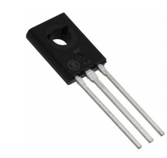
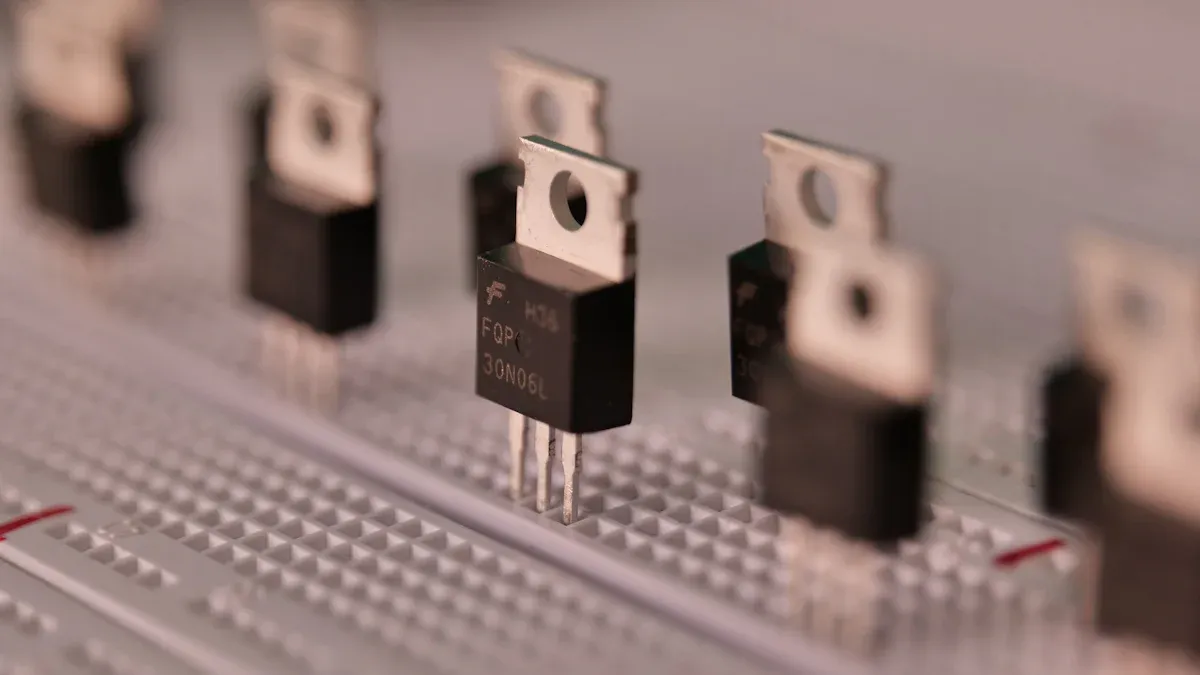
Comes in TO-126 or TO-220 packages. These help with heat and let it work in hard places.
-
Works in many uses, like switch-mode power supplies, voltage regulators, audio amplifiers, and electronic ballasts.
-
It is not expensive and you can find it easily. You can use it for hobby or professional projects.
You will see that the mje13003 transistor is a flexible npn transistor. It gives good performance for the price. This makes it a top pick for many power transistor uses. It may not have the highest gain or frequency response. Still, you can trust the mje13003 transistor to work well and reliably in most power circuits.
13003 Transistor Pinout
Pin Configuration
You need to know the correct pin configuration before you use the 13003 transistor in your project. The 13003 transistor usually comes in a TO-220 or TO-126 package. When you look at the flat side of the transistor with the pins facing down, you will see three pins. From left to right, the pins are Emitter (E), Base (B), and Collector (C). This pin configuration is common for many power transistors, but you should always check the datasheet or a pinout diagram to be sure.
Here is a table that compares the pin configuration and ratings of the 13003 transistor with other popular power transistors:
|
Transistor |
Pin Configuration (from front view) |
Max Collector Current (Ic) |
Collector-Emitter Voltage (Vceo) |
|---|---|---|---|
|
13003 (MJE13003) |
Emitter (E), Base (B), Collector (C) |
1.5 A |
400 V |
|
2N3055 |
N/A (standard TO-3 package) |
15 A |
60 V |
|
TIP3055 |
N/A (TO-220 package) |
15 A |
60 V |
|
MJ15003 |
N/A (TO-3 package) |
20 A |
140 V |
|
2SD882 |
N/A (TO-126 package) |
3 A |
40 V |
You can see that the 13003 transistor has a lower collector current than some other power transistors, but it can handle much higher voltages. This makes it a good choice for high-voltage, moderate-current circuits.

📝 Tip: Always double-check the pin configuration before you connect the transistor. A wrong connection can damage your component or the whole circuit.
Identifying Pins
You can identify the pins of the 13003 transistor by looking at the flat side of the package. Hold the transistor so the writing faces you and the pins point down. The first pin on the left is the Emitter, the middle pin is the Base, and the right pin is the Collector. This simple layout helps you avoid mistakes when you build your pinout and circuit.
If you want to be extra sure, you can use a multimeter to test the pins. Set the meter to diode mode. Place the positive lead on the Base and the negative lead on the Emitter. You should see a small voltage drop. Do the same with the Collector. This test helps you confirm the pinout if you do not have a pinout diagram.
You will often find the 13003 transistor in power supply circuits, so knowing the pinout is very important. When you follow the correct pin configuration, your pinout and circuit will work safely and efficiently.
MJE13003 Datasheet
Key Specifications
When you check the datasheet for the mje13003, you find important numbers. These numbers help you know if this transistor is right for your power circuit. The datasheet pdf shows the highest voltage, current, and power it can take. These values tell you how much the mje13003 can handle before it breaks. You should always look at these numbers before using the transistor.
Here is a table with the main specifications you will see in the datasheet:
|
Specification |
Value/Range |
Impact on Performance in Power Circuits |
|---|---|---|
|
Maximum Collector Current (Ic) |
1.5 Amperes |
Defines max current transistor can handle, critical for load capacity. |
|
Collector-Emitter Voltage (Vceo) |
400 Volts |
Maximum voltage between collector and emitter, important for voltage tolerance. |
|
Collector-Base Voltage (Vcbo) |
700 Volts |
Maximum voltage between collector and base, affects breakdown voltage. |
|
Emitter-Base Voltage (Vebo) |
9 Volts |
Voltage required to bias the transistor, influences switching behavior. |
|
DC Current Gain (hfe or β) |
25 to 100 |
Determines amplification capability, affecting efficiency and gain. |
|
Power Dissipation (Pd) |
25 Watts |
Maximum power the transistor can dissipate, relates to thermal limits. |
|
Transition Frequency (fT) |
~2 MHz |
Indicates switching speed, important for high-frequency applications. |
|
Operating Temperature Range |
-65°C to +150°C |
Defines safe operating temperature, impacts reliability and durability. |
You can see the mje13003 has high voltage ratings. It works in many power circuits. The datasheet pdf also shows it can handle heat and switch quickly.
📝 Note: Always use the numbers from the datasheet. This keeps your circuit safe and helps your design work well.
Electrical Characteristics
The mje13003 datasheet gives more details about how the transistor works. You will see values for collector-emitter voltage, collector-base voltage, and emitter-base voltage. The datasheet also lists the highest collector current and power it can handle. These electrical details help you pick the mje13003 for your project.
Here is a table with the main electrical details:
|
Parameter |
Typical Value |
|---|---|
|
Collector-Emitter Voltage (Vceo) |
400 Volts |
|
Collector-Base Voltage (Vcbo) |
700 Volts |
|
Emitter-Base Voltage (Vebo) |
9 Volts |
|
Maximum Collector Current (Ic) |
1.5 Amperes |
|
Power Dissipation (Pd) |
25 Watts |
|
DC Current Gain (hfe or β) |
25 to 100 |
|
Package Type |
TO-220 |
|
Operating Temperature Range |
-65°C to +150°C |
You should always match the datasheet numbers to your circuit needs. If you go over the voltage or power limits, you might break the mje13003. The datasheet pdf gives you all the numbers you need to stay safe.
⚡ Tip: Use the datasheet as your main guide when you build or fix power circuits with the mje13003. This helps you make safe and strong electronics.
Power Circuit Integration
Connection
You can use the 13003 transistor in a power circuit by following easy steps. First, find out the pinout and look at your circuit layout. Hold the transistor so the flat side faces you and the pins point down. The left pin is the emitter. The middle pin is the base. The right pin is the collector.
To use the 13003 transistor as a switch, do these steps:
-
Connect the emitter pin to the ground in your circuit.
-
Attach the collector pin to one side of your load, like a lamp or motor.
-
Connect the other side of the load to the positive voltage supply.
-
Put a resistor (from 1kΩ to 10kΩ) between the base pin and your control signal. This keeps the base current safe.
-
To protect the transistor from voltage spikes, add a flyback diode across the load. This is important if you use motors or relays.
⚡ Tip: Always check the pinout before you solder or turn on your circuit. A wrong connection can break the transistor or the whole circuit.
Example Circuits
The 13003 transistor works in many types of circuits. Here are two simple examples:
1. Simple Power Switch Circuit
This circuit lets you turn a high-voltage load on or off with a low-voltage signal.
+V (Power Supply)
   |
  [Load]
   |
Collector (13003)
   |
Emitter (13003)
   |
 Ground
Base (13003) --[Resistor]-- Control Signal
-
The control signal turns the transistor on or off.
-
The load gets power only when the transistor is on.
2. Switch-Mode Power Supply (SMPS) Circuit
The 13003 transistor is good for SMPS circuits. In these circuits, the transistor switches power on and off very fast. This helps change voltage and makes the circuit work better.
-
The base gets a pulsed signal from an oscillator.
-
The collector connects to the main winding of the transformer.
-
The emitter goes to ground.
-
Add a snubber circuit (resistor and capacitor) across the collector and emitter. This protects the transistor from voltage spikes.
💡 Note: Always use the right value for each part. The wrong value can make the circuit not work or overheat the transistor.
Tips
You can make your circuits safer and better by following these tips:
-
Limit Inrush Current: Use a capacitor (like 20µF) to stop a big rush of current when you turn on the circuit. This keeps the 13003 transistor safe. Pick the capacitor size by checking application notes to fit your circuit.
-
Add Series Resistors: Put a resistor (about 10Ω, 1W) in series with the power supply or base. This resistor limits the starting current and helps stop transistor failure.
-
Use Voltage Regulators and Filtering: Add a voltage regulator (such as the 7805 IC) and filter capacitors after the rectifier. These parts keep the voltage steady and lower ripple. This protects the transistor and other parts.
-
Zero Crossing Switching: If you use the 13003 transistor in AC circuits, try zero crossing detection. This switches the circuit when the AC voltage is at zero. It lowers stress on the transistor.
-
Choose the Right Components: Pick parts that match the voltage and current your circuit needs. For example, the MJE13005 transistor can be safer in some power supplies.
-
Follow Application Notes: Always read the manufacturer’s application notes for help with picking capacitors and other parts. This helps you avoid mistakes.
|
Practical Tip |
Description |
Supporting Detail |
|---|---|---|
|
Inrush Current Limiting |
Use capacitors and inductors to limit surge current during power-on |
A 220uF/50V capacitor keeps base voltage low; an inductor gives high resistance at switch-on |
|
Series Resistor for Limiting |
Add series resistors (~10Ω, 1W) to limit startup current |
Resistors R2 + R3 limit inrush current during startup |
|
Voltage Regulation and Filtering |
Use voltage regulators and filter capacitors |
Voltage regulators keep output steady; filter capacitors lower ripple and stress |
|
Zero Crossing Switching |
Use zero crossing detection with opto-triac drivers |
MOC series optocouplers handle zero crossing, lowering inrush current |
|
Component Selection |
Pick the right transistors for your circuit |
MJE13005 gives better safety and works well in some power supplies |
📝 Tip: Always test your pinout and circuit on a breadboard before making it permanent. This helps you find mistakes early and keeps your parts safe.
You can avoid many mistakes by using these tips. Always check your connections, use the right values, and protect your transistor from inrush current. These steps help your 13003 transistor work well in all your circuits.
MJE13003 Transistor Applications
Switch-Mode Power Supplies
You will find the mje13003 transistor in switch-mode power supplies. These circuits need fast and steady switching. The mje13003 is good for this because it handles high voltages and medium currents. Using this transistor helps you make power management work well for many devices.
In switch-mode power supplies, the mje13003 turns current on and off very fast. This helps change voltage and keeps energy loss low. You can see this transistor in chargers, adapters, and small electronics. The mje13003 also protects your circuit by turning off if there is too much current.
⚡ Tip: Always look at the datasheet before using the mje13003 in your circuit. This helps you stop damage and keeps your design safe.
Here are some reasons to use the mje13003 in switch-mode power supplies:
-
Handles high voltage easily
-
Switches fast for better efficiency
-
Fits well in small circuits
Power Amplifiers
You can use the mje13003 transistor in power amplifiers too. These circuits need a part that can make signals bigger and run speakers or motors. The mje13003 gives enough current gain to make your amplifier strong and clear.
In audio amplifiers, the mje13003 makes the sound signal bigger. This gives you louder and better sound from your speakers. In other high-power circuits, this transistor can run motors or other loads that need more power.
|
Application Area |
Why Use mje13003? |
|---|---|
|
Audio Amplifiers |
Good current gain, clear output |
|
Motor Drivers |
Handles medium loads easily |
|
Signal Boosters |
Reliable for circuit applications |
You can trust the mje13003 transistor for many power switching jobs. It works well in both switch-mode power supplies and power amplifiers. This makes it a smart pick for your circuits and other high-power uses.
13003 Transistor Equivalents
Common Replacements
If you need to swap out a 13003 transistor, you have some choices. These other transistors can do similar jobs in power circuits. But you should always check their ratings before picking one. Here is a table that lists some popular replacements for the 13003 transistor:
|
Equivalent Transistor |
Max Collector Current (Ic) |
Max Collector-Emitter Voltage (Vceo) |
Suitability Reason |
|---|---|---|---|
|
2N3055 |
15 A |
60 V |
Similar ratings to 13003, suitable for similar power applications |
|
TIP3055 |
15 A |
60 V |
Similar to 2N3055 and 13003, widely used power transistor |
|
MJ15003 |
20 A |
140 V |
Higher power rating, suitable for more demanding applications |
|
2SD882 |
3 A |
40 V |
Lower power equivalent, suitable for smaller applications |
Each replacement has its own good points. Some can handle more current. Others work with lower voltages. If you want to see how they compare, look at the chart below:

💡 Tip: Always make sure the voltage and current ratings match your circuit. This keeps your project safe and stops damage.
Selection Criteria
You should think about a few things when picking a replacement for the 13003 transistor. Not every replacement will work the same in every circuit. Here are some important things to help you choose:
-
The 13003 transistor can handle up to 400 V. This is much higher than some like the 2N3055 or TIP3055. If your circuit uses high voltage, pick a replacement with a similar voltage rating.
-
The 13003 can handle about 1.5 A collector current. Some replacements, like the 2N3055, can take more current. You can use them for bigger loads, but check if the voltage is enough.
-
The 13003 switches on and off quickly. This makes it better for fast circuits than some slower replacements.
-
Power dissipation for the 13003 is about 25 W. Some replacements can handle more power, but always check the datasheet.
-
The 13003 works in hot and cold places. This makes it reliable in tough spots.
-
Price is important too. The 13003 is cheap, but some replacements may cost more.
📝 Note: Always test your replacement in your real circuit before using it for good. Even small changes can affect how your project works.
If you follow these tips, you can find the best replacement for your needs. Always check the datasheet and compare the ratings. This helps you pick the right part and keeps your circuits working well.
Best Practices
Safe Operation
You want your circuits to work safely and last a long time. Start by buying your 13003 transistors from trusted sources. Many fake power transistors exist. These counterfeits can fail early and damage your equipment. You can avoid these problems by following a few simple steps:
-
Buy transistors directly from original manufacturers like OnSemi, Fairchild, or Linear. These companies have a strong reputation for quality.
-
Check the markings on your transistor. Genuine parts use permanent ink. If you can remove the markings with acetone, the part is likely fake.
-
Look at the case material. Real transistors often use steel cases. Some fakes use aluminum, but some also mimic steel, so this is not the only check.
-
Test the transistor if you have the tools. Genuine devices show a steady relationship between base current and collector current. Fakes often do not.
⚠️ Tip: Counterfeit transistors can destroy expensive parts in your circuit. Always stay alert and report any suspicious parts to your supplier.
When you build your circuit, always double-check the pinout. Use the right resistor values to protect the base. Add a flyback diode if you switch inductive loads. These steps help keep your transistor and other parts safe.
Troubleshooting
If your circuit does not work, you can follow a few steps to find the problem. Start by checking your connections. Make sure you did not mix up the emitter, base, and collector pins. A wrong connection can stop the transistor from working.
-
Use a multimeter to test the transistor. In diode mode, check for a small voltage drop between the base and emitter, and between the base and collector.
-
Look for signs of overheating. If the transistor feels hot, you may have used the wrong resistor or connected it incorrectly.
-
Replace the transistor with a known good one if you suspect it is faulty. Sometimes, even new parts can be bad if they are counterfeit.
-
Check your power supply voltage. Too much voltage can damage the transistor. Too little voltage can stop the circuit from working.
🛠️ Note: If you keep having problems, try building the circuit on a breadboard first. This makes it easier to spot mistakes and fix them before you make the final version.
By following these best practices, you can keep your circuits safe and working well. You also lower the risk of damage from fake parts or wiring mistakes.
When you use the 13003 transistor in power circuits, always check the pinout. You should also follow the datasheet limits for safety. The table below shows the right pinout for safe connections:
|
Pin Number |
Pin Name |
Description |
|---|---|---|
|
1 |
Emitter |
Current leaves the transistor |
|
2 |
Base |
This pin controls how the transistor works |
|
3 |
Collector |
Current goes into the transistor |
You keep your circuit safe by knowing the voltage, current, and power ratings. If you follow these best practices, your designs will work well and last longer.
FAQ
What is the maximum voltage you can use with the 13003 transistor?
You can use the 13003 transistor with voltages up to 400V between collector and emitter. Always check the datasheet for your specific part before building your circuit.
How do you test if a 13003 transistor works?
Set your multimeter to diode mode. Place the positive lead on the base and the negative lead on the emitter. You should see a small voltage drop. Repeat with the collector. No reading means the transistor may be faulty.
Can you use the 13003 transistor for audio amplifiers?
Yes, you can use the 13003 transistor in simple audio amplifier circuits. It provides enough current gain for small speakers. For high-quality sound, you may want a transistor with higher gain.
What happens if you connect the pins incorrectly?
If you connect the pins wrong, the transistor will not work. It may overheat or get damaged. Always double-check the pinout before powering your circuit.