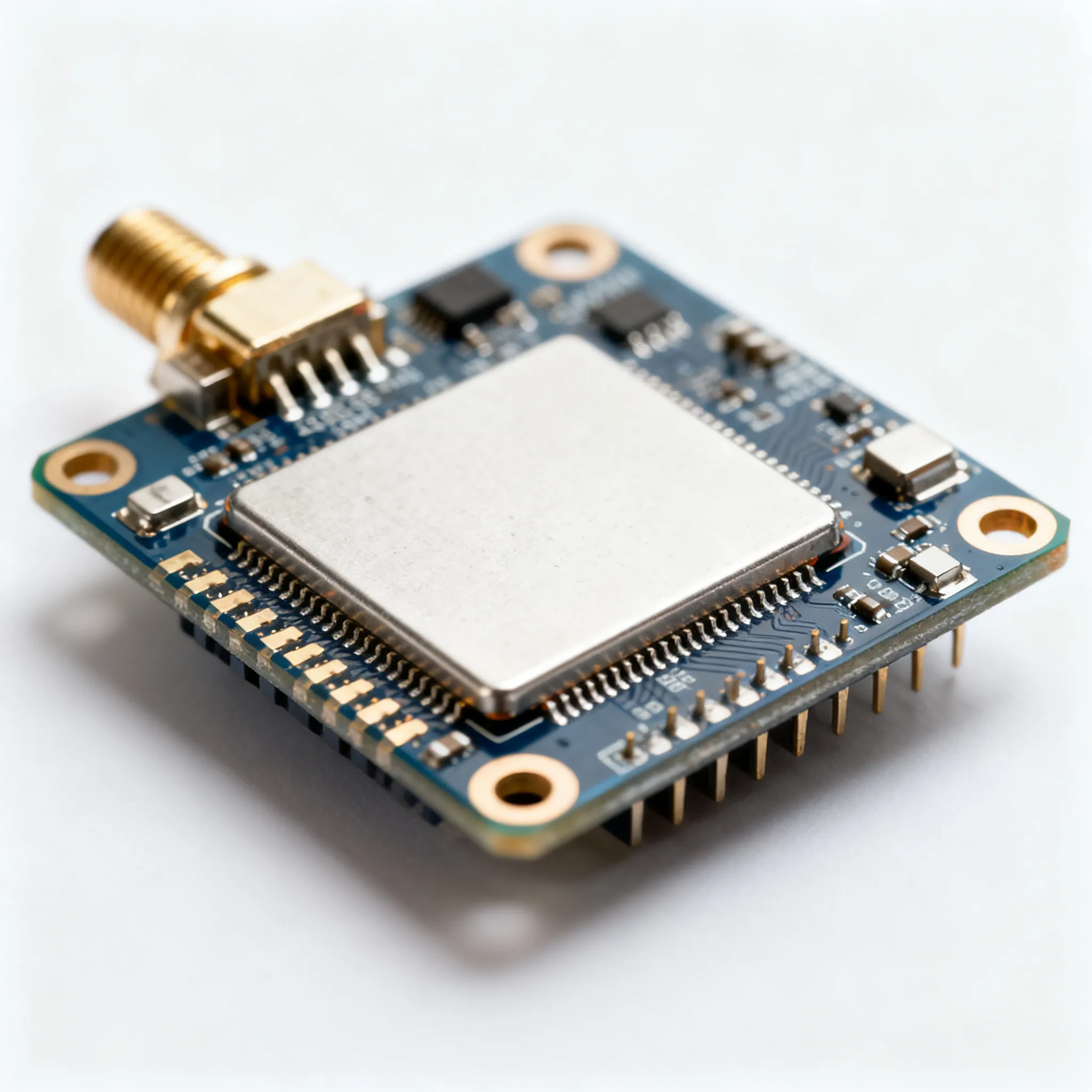
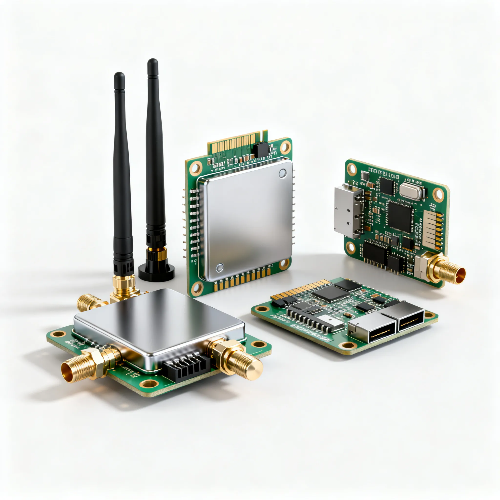
How to Troubleshoot Common Issues with Components Assembled PCB in Intelligent Sensing Solutions
Printed Circuit Boards (PCBs) are key parts of smart sensors. Even the best designs can have problems. To troubleshoot common issues effectively, fixing these problems helps your system work well.
Printed Circuit Boards (PCBs) are key parts of smart sensors. Even the best designs can have problems. To troubleshoot common issues effectively, fixing these problems helps your system work well. Issues often arise from bad soldering or heat control during assembly. Wrongly placed parts can disrupt signals and power flow, leading to connection problems. Bad solder joints create weak connections, while heat stress can damage parts over time. Finding these problems early is crucial to keep your PCBA strong and functioning properly.
Key Takeaways
-
Look at your PCB carefully for cracks or burn marks. Finding problems early stops bigger issues later.
-
Use tools like multimeters and oscilloscopes to check connections. These tools help find problems exactly.
-
Clean your PCB often and check for damage. Regular care keeps it working well for a long time.
-
Pick good materials and use proper soldering when building. Good methods lower the chance of mistakes.
-
Change old or broken parts quickly. Keeping parts in good shape makes your smart sensors work better.
Finding and Fixing Common PCB Problems
Broken Parts in PCB Assembly
Broken parts are a common problem in PCB assembly. You may find damaged resistors, capacitors, or chips. These problems happen due to bad handling, poor storage, or factory mistakes. For example, too much moisture can ruin parts, causing them to fail. Placing parts in the wrong spots during assembly can also cause power and signal issues.
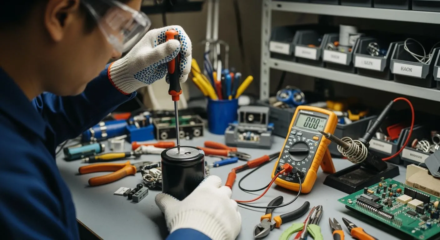
To find broken parts, start by looking at the board. Check for cracks, burns, or other damage. Use a multimeter to test if parts work properly. Handling and storing parts carefully can stop these problems in future designs.
Connection Issues in Smart Sensors
Connection issues can hurt how smart sensors work. These problems come from bad soldering, broken lines, or misplaced connectors. Weak soldering can cause loose connections. Broken lines can stop power or signals completely. Misplaced connectors can block communication between parts.
To fix connection issues, check the soldering closely. Look for dull or cracked solder spots. Use a multimeter to find broken lines. Make sure connectors are placed correctly during assembly to keep connections strong.
Signal Problems in PCB Circuits
Signal problems can mess up how your PCB works. This happens because of bad layouts, poor grounding, or electromagnetic noise. When signals mix or clash, it can cause errors or slow performance in smart sensors.
To fix signal problems, check the PCB layout. Keep high-frequency signals away from sensitive parts. Use good grounding to reduce noise. Adding shields to important areas can also help signals stay clear. Planning these steps during design can lower the chance of signal issues.
Performance Problems in PCB Work
Performance problems in PCBs can make smart sensors unreliable. These problems often happen because of bad heat control, old parts, or design mistakes. If a PCB doesn’t work right, it might give wrong sensor readings or stop working completely.
To find these problems, watch how the system acts. Look for things like changing outputs, slow responses, or sudden shutdowns. These signs often mean issues like overheating or worn-out parts. Use tools like oscilloscopes to check signals and test the circuit.
Keeping the PCB cool is very important. Too much heat can break solder joints and harm parts. Make sure heat sinks, cooling pads, or fans are set up correctly. Check for dust often, as it can block airflow and make heat problems worse.
Old parts can also cause trouble. Over time, capacitors may stop holding charge, and resistors may lose accuracy. Replacing old parts can help the PCB work better again.
Bad designs, like wrong trace paths or poor grounding, can create issues too. Check the PCB layout to see if power and signal paths are correct. Keep high-frequency signals away from sensitive lines to avoid interference.
Fixing these problems step by step can make your smart sensors work better. Regular checks and tests can catch problems early and keep the system stable for a long time.
Step-by-Step Guide to Fix Common PCB Problems
Checking the PCB by Looking Closely
Start by carefully looking at the PCB. This helps you find problems like misplaced parts, bad soldering, or broken lines. Check the solder joints closely. Bad soldering can cause loose connections or open circuits. Look for cracks, missing solder, or uneven spots. These mistakes can weaken your PCB and cause it to work poorly.
Make sure parts are in the right place. Misaligned parts can mess up power and signals. Use a magnifying glass to see small details. Look for burnt spots or discoloration, which show overheating during assembly. Finding these problems early keeps your PCB strong and working well.
Using Tools to Test the PCB
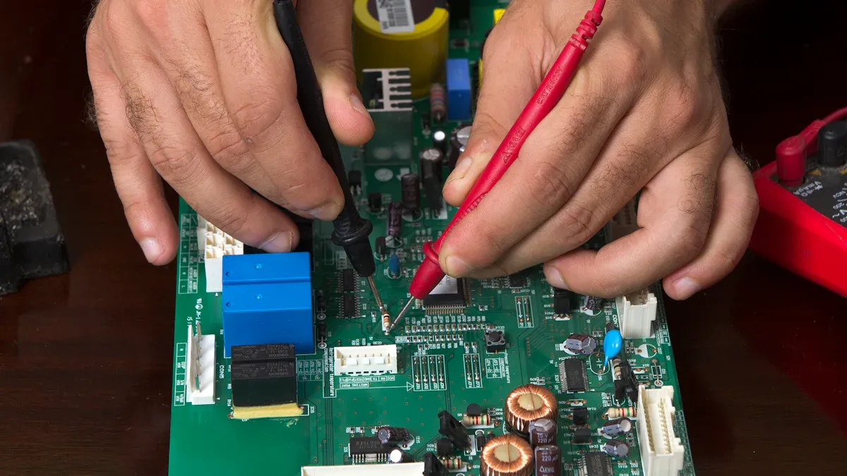
After checking visually, use tools like multimeters and oscilloscopes. A multimeter measures voltage, resistance, and if circuits are connected. Use it to find broken lines, short circuits, or wrong power levels. For example, if a part isn’t getting power, follow the circuit to find the problem.
Oscilloscopes check signals on the PCB. They show if signals are clear or have errors like noise. Attach the probes to test points on the board. Watch the waveforms to see if they look right. If something seems off, check nearby parts or lines for issues. These tools give accurate data to help fix problems.
Using Software to Find PCB Errors
Software tools are great for finding PCB errors. They use smart programs to detect problems quickly and accurately. These tools save time and effort by finding issues faster. They also test the PCB in different ways to make sure everything works.
One big benefit is that anyone can use these tools. You don’t need to be an expert to get good results. They make fixing problems easier for everyone. Plus, they save money and time by speeding up the process.
Here’s a simple table about software tools:
|
Feature |
What It Does |
|---|---|
|
Smart Error Detection |
|
|
Accurate Testing |
Finds issues correctly, avoiding missed problems. |
|
Different Testing Methods |
Tests the PCB in many ways for full checks. |
|
Easy to Use |
Works well even if you’re not an expert. |
|
Saves Time and Money |
Makes fixing problems faster and cheaper. |
Using software tools in your process helps you fix problems faster and keeps your PCB working well.
Fixing or Swapping Broken PCB Parts
If a PCB isn’t working, broken parts are often the cause. Fixing or replacing these parts can make it work again. Follow these steps to solve common problems and fix your PCB properly.
1. Find the Broken Part
First, figure out which part is causing trouble. Use tools like a multimeter to check for bad connections, wrong power levels, or damaged parts. Look for signs like burns, cracks, or discoloration. Parts like capacitors, resistors, and chips often fail due to heat, bad placement, or factory mistakes.
Tip: Keep your PCB design map nearby. It helps you find parts faster.
2. Take Out the Broken Part
After finding the bad part, carefully remove it from the PCB. Heat the solder joints with a soldering iron, then use a pump or wick to take out the melted solder. Be gentle to avoid harming nearby parts or the board.
-
Steps to Remove Safely:
-
Heat the solder joint with the iron.
-
Use a pump to remove the melted solder.
-
Lift the part gently with tweezers.
-
3. Get the PCB Ready for a New Part
Once the broken part is out, clean the area for the new one. Use alcohol and a soft brush to clear leftover solder or dirt. Check if the pads are damaged. Fix broken pads with conductive glue or copper tape.
Note: Broken pads can mess up signals and power. Fixing them helps the new part work well.
4. Put in the New Part
Place the new part in the right spot on the PCB. Make sure it’s lined up correctly. Use a soldering iron and fresh solder to attach it. Use just enough solder to make a strong connection without causing shorts.
-
Tips for Good Soldering:
-
Use a small-tip soldering iron for accuracy.
-
Spread solder evenly on the pad and part lead.
-
Don’t overheat to avoid damaging the part.
-
5. Test the Fixed PCB
After adding the new part, test the PCB to see if it works. Use a multimeter to check connections and power. An oscilloscope can check if signals are clear. If there’s still a problem, check the solder joints and part placement again.
6. Solve Common Problems
Fixing parts can sometimes create new issues. For example, bad soldering can make weak connections, and too much heat can harm parts. To avoid this:
-
Use good-quality solder and flux for better results.
-
Keep the heat steady while soldering.
-
Check the PCB design to ensure parts are placed correctly.
Pro Tip: Regular checks can stop problems before they start. Inspect your PCB often to catch issues early.
By following these steps, you can fix or replace broken parts easily. This not only solves current problems but also helps your PCB last longer.
Preventative Measures for Reliable PCB Performance
Best Practices to Avoid PCB Assembly Process Defects
Stopping defects during assembly keeps your PCBA working well. Following simple steps can lower mistakes and improve quality. Here’s how:
-
Use High-Quality Materials
Pick strong parts and materials for your PCBA. Good solder and paste make solid connections and prevent weak spots. Bad materials can cause cracks or broken circuits. -
Ensure Proper Solder Paste Application
Spread solder paste evenly and use the right amount. Uneven paste can cause bridges or weak links. Use machines for smooth application and check under a microscope for mistakes. -
Optimize Component Placement
Place parts correctly to avoid misalignment. Misplaced parts can mess up signals and cause problems. Use machines to place parts accurately and double-check before soldering. -
Control Temperature During Soldering
Keep the right heat level while soldering. Too much heat can harm parts, and too little can make weak joints. Use ovens with controlled heat zones for better results. -
Inspect the Assembly Process Regularly
Check the assembly often for mistakes like missing parts or bad soldering. Finding problems early keeps your PCBA strong.
Tip: Make a checklist to follow during assembly. It helps avoid errors and keeps the process consistent.
Regular Maintenance and Testing for Intelligent Sensing PCBs
Taking care of your PCBA regularly helps it last longer. Smart sensing systems need steady performance, which comes from good maintenance. Follow these steps:
-
Clean the PCB Regularly
Dust can build up and hurt performance. Use a soft brush or air to clean it. For sticky dirt, use alcohol and a cloth to clean without damage. -
Check for Physical Damage
Look for cracks, burns, or broken solder joints. Damage can cause errors. Fix problems quickly to stop them from getting worse. -
Test Electrical Connections
Use a multimeter to check if circuits work. Look for broken lines or wrong power levels. Regular testing finds problems early. -
Monitor Component Performance
Parts like capacitors and resistors can wear out over time. Use tools to test them and replace old or failing parts. -
Update Firmware and Software
Smart systems need updated programs to work well. Keep software current to fix bugs and stay compatible with new tech. -
Perform Functional Testing
Test the whole PCBA to see if it works right. Simulate real-world use to find hidden issues. Testing ensures everything runs smoothly.
Pro Tip: Plan regular checks and write down all tests and fixes. This helps track your PCBA’s condition and keeps it reliable.
By following these steps, you can reduce mistakes, make your PCBA last longer, and keep your smart sensing systems dependable.
Careful troubleshooting helps your PCB work well in smart sensors. Finding problems like broken parts or signal issues early saves money. Use tools like multimeters and oscilloscopes to locate issues. Fix them step by step for better results. Regular care and good assembly habits keep your PCB strong. Cleaning and testing often can make your system last longer. By focusing on these steps, you ensure steady performance and long-term success.
FAQ
1. What tools can help fix PCB problems?
Use multimeters to check voltage and resistance. Oscilloscopes show signal patterns. Software tools find errors fast and accurately.
2. How do you stop PCBs from overheating?
Add heat sinks, cooling pads, or fans to control heat. Clean dust often to keep airflow clear. Use proper heat settings during assembly to avoid overheating.
3. Why is it important to maintain intelligent sensing PCBs?
Maintenance keeps your PCB working well. Clean it, test connections, and replace old parts. This stops failures and makes your system last longer.
4. What are signs of broken PCB parts?
Check for cracks, burns, or discoloration. If the system shuts down, gives wrong readings, or slows down, parts might be failing.
5. How can you make PCB assembly better?
Choose good materials and spread solder paste evenly. Place parts correctly and inspect often to catch mistakes early. This ensures better performance.