

PCB Assembly: Main Processes, Technologies, and Quality Control
PCB assembly is when you put and solder electronic parts onto a printed circuit board. This makes the circuits work. People use this process to make electronics that work well every day.
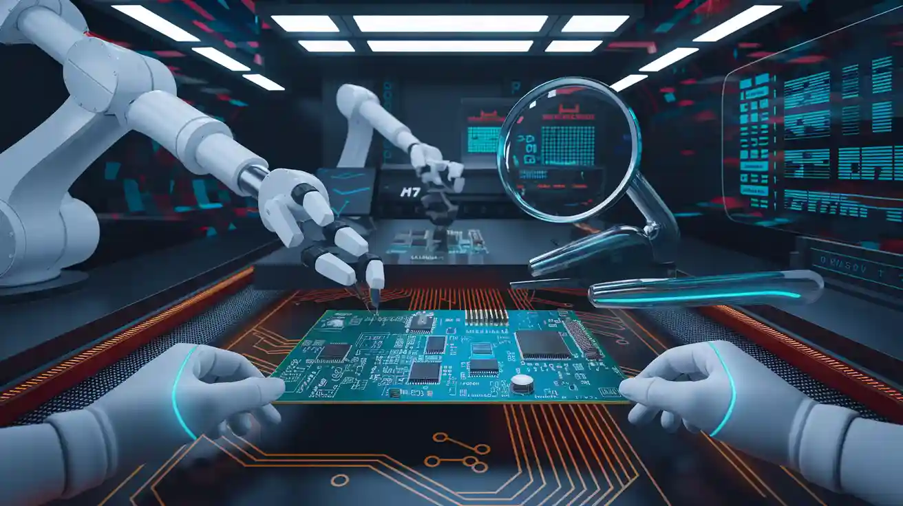
PCB assembly is when you put and solder electronic parts onto a printed circuit board. This makes the circuits work. People use this process to make electronics that work well every day. Machines help put parts in the right place with ±0.01 mm accuracy. These machines can place over 20,000 parts each hour. This lowers the need for workers by up to 70%. If you learn the main steps and new methods in printed circuit board assembly, you can make better products. This also helps stop mistakes and makes sure your circuits work right.
Aspect
Description / Statistic
Placement Accuracy
±0.01 mm
Throughput Rate
Over 20,000 parts per hour (CPH)
Labor Cost Reduction
Up to 70% less because of machines
Key Takeaways
-
PCB assembly puts electronic parts on boards. This helps devices work better and last longer. Good design and planning save time and money. They also help stop mistakes during assembly. Machines place parts quickly and very accurately. This means less work for people and fewer errors. Quality control uses AOI, X-ray, and testing tools. These tools find problems early and make sure products work well. Following industry standards keeps PCB products safe and strong. It also helps people trust these products.
PCB Assembly Overview
What Is PCB Assembly
You use pcb assembly to put electronic parts on a pcb. This makes circuits that help devices work. You begin with a plain pcb. It has copper lines and pads. The copper lines move electricity to each part. In assembly, you add things like resistors, capacitors, and chips. Machines or people can do this job. Next, you solder the parts to the board. Soldering keeps the parts in place and lets electricity flow. This step changes a simple board into a working device.
Tip: Always look over your design before you start assembly. A good design helps you stop mistakes and saves time.
Purpose of Printed Circuit Board Assembly
You need printed circuit board assembly to make strong electronics. The main goal is to build circuits that work right. When you put together a pcb, you check that each part is in the right place. You also make sure every connection is tight. This helps stop short circuits and other issues. You can use pcb assembly for things like computers, phones, and cars. Each step in assembly makes your device better and stronger.
-
Key reasons for pcb assembly:
-
It turns your design into something real.
-
It makes sure your circuits are safe.
-
It helps you make lots of electronics at once.
-
It lets you follow industry rules.
-
You count on pcb assembly to help your devices last longer and work better.
PCB Assembly Process
Design for Assembly (DFA)
The pcb assembly process begins with design for assembly. This step makes your pcb easier to build and more dependable. If you think about manufacturability early, you avoid mistakes and delays. Planning ahead saves both time and money.
-
Good designs move through assembly quickly, so products reach customers sooner.
-
Using less material and labor helps lower costs.
-
PCBs made with DFA are stronger and ready for making.
-
Most of your product’s cost comes from the design. Smart choices can lower your bill of materials, cut assembly time, and make your product last longer.
-
If you use only surface mount devices on one side, you can solder everything in one step. This saves time and keeps things simple.
-
Fewer parts mean less handling and faster paperwork, which makes work easier and profits better.
Tip: Always check your design before you start assembly. A simple and well-planned design makes everything go smoother.
Solder Paste Application
Next, you put solder paste on the pcb. This step is important because it holds parts in place before soldering. You use a stencil to spread paste over the pads. Stencil printing can cover up to 10,000 pads each hour, so you can work fast. This method keeps defect rates below 1% in big production runs, which means good quality.
Jet dispensing is another way to apply paste. It gives placement accuracy of ±0.025 mm and keeps the paste amount steady. You use at least three fiducial marks on each pcb to line up the stencil and avoid mistakes. Multi-level stencils help you put the right amount of paste on different parts. A good stencil design, with the right hole size and thickness, stops problems like overheating or weak joints.
-
Stencil printing is fast for big jobs
-
Low defects in mass production
-
Jet dispensing is accurate and repeatable
-
Fiducial marks help with proper alignment
-
Multi-level stencils let you use custom paste amounts
SMD and THT Placement
After putting on solder paste, you place parts on the pcb. There are two main ways: Surface Mount Device (SMD) placement and Through-Hole Technology (THT) placement. SMD placement uses machines to put small parts on top of the board. THT placement puts parts through holes in the pcb.
|
Case Study |
Reported Success Metrics and Improvements |
|---|---|
|
Consumer Electronics |
|
|
Manufacturer |
Defect rates reduced from 2% to 0.02% |
|
New product launches accelerated by 65% |
|
|
Labor costs per unit decreased by 78% |
|
|
Automotive Electronics |
First-pass success rate improved from 92% to 99.7% |
|
Supplier |
Warranty claims dropped by 83% |
|
Medical Device Startup |
Monthly production scaled from 100 to 5,000 units |
|
Time-to-market shortened from 18 months to 7 months |
SMD placement makes things faster and lowers mistakes. THT placement gives strong and steady connections, which are needed for parts that handle stress.
Soldering
Now it is time for soldering. This step melts the solder paste and makes strong electrical links between parts and the pcb. You can use reflow soldering for SMD parts or wave soldering for THT parts. New soldering methods, along with careful checking and testing, can lower defects by up to 90%. This means your boards work better and last longer.
Good soldering keeps your circuits safe and working well. Bad soldering can cause failures and expensive repairs.
Cleaning
After soldering, you clean the pcb to get rid of leftover flux or residue. Clean boards stop problems like rust, bad coating, and electrical failures.
-
You look for visible residue using a magnifier.
-
You use ionic contamination tests to keep residue below 1.56 µg/cm² NaCl, which is important for sensitive electronics.
-
If you find stubborn residue, you may need to change your cleaning method or use a new solvent.
-
Cleanliness is important for the reliability and performance of your pcb assembly.
Inspection and Testing
The last step in pcb assembly is inspection and testing. You use different ways to make sure your boards meet quality rules.
-
You check parts before assembly to find damage or defects.
-
You check solder paste for the right height and placement.
-
Automated Optical Inspection (AOI) uses cameras to find missing parts or soldering problems.
-
X-ray inspection lets you see inside solder joints to find hidden issues.
-
In-circuit testing checks if the board works as it should.
Statistical Process Control (SPC) helps you watch data during production. This lets you spot problems early and fix them. Fewer defects mean less waste and better reliability. Good inspection and testing improve performance and save money by stopping rework and warranty claims.
-
Automated inspection gives fast and steady results.
-
Training makes sure everyone uses the tools the right way.
Note: Careful inspection and testing at every step help you deliver reliable, high-quality pcb assemblies.
Printed Circuit Board Technologies
Surface Mount Technology (SMT)
Surface Mount Technology puts small parts right on the pcb’s surface. This lets you fit more parts in a tiny area. Machines can place many parts every hour, so assembly goes fast. You see SMT in things like phones and computers. This way helps make devices light and small. SMT also saves money because you do not need as much drilling or material.
-
SMT is great for making lots of products.
-
It makes assembly quicker and cuts down on mistakes.
-
You can design smaller and trickier pcb shapes.
💡 SMT is best when you want quick, machine-made, and packed pcb assembly.
Through-Hole Technology (THT)
Through-Hole Technology uses holes drilled in the pcb. You put part leads into these holes and solder them underneath. THT gives strong and steady connections, good for parts that get hot or stressed.
-
THT is good for special parts that need hands-on work.
-
This way is cheaper for test runs or small groups.
-
The steps are planning, putting in parts, soldering, and cleaning.
-
Careful soldering and checking make sure it lasts a long time.
|
Aspect |
Evidence Supporting Reliability |
|---|---|
|
Through-hole parts go in drilled holes, so they handle stress well, even in tough places like planes. |
|
|
Strong Soldered Connection |
Pins soldered through holes make steady, strong links that last. |
|
Enhanced Testability |
Testing all leads makes sure the board works right and stays reliable. |
|
Ease of Debugging |
Putting in parts by hand makes it easy to swap out bad ones and fix problems. |
|
Quality Assurance |
Careful checks like AOI, ICT, and FPT look at solder and the whole board. |
|
Soldering Methods |
Using hand and wave soldering makes sure joints are neat and always the same, which is important for trust. |
|
Cleaning Process |
Cleaning after soldering gets rid of extra stuff and stops shorts or rust, so the board lasts longer. |
Hybrid Assembly
Hybrid assembly uses both SMT and THT on one pcb. You pick this way if you need lots of parts close together and some parts that must be strong. Hybrid assembly lets you get both benefits.
|
Performance Indicator |
Value |
Description |
|---|---|---|
|
Assembly Success Rate |
Most PCB kit-box build assembly (PKBA) tasks work with hybrid assembly. |
|
|
Placement Error Margin (linear) |
< 0.8 mm |
Most part placement mistakes are less than 0.8 mm. |
|
Placement Error Margin (angular) |
< 0.6 degrees |
Most angle mistakes are less than 0.6 degrees. |
|
Assembly Quality Improvement |
65.61% |
Hybrid digital twin models make assembly quality better by over 65%. |
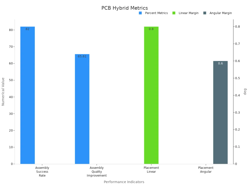
Hybrid assembly makes boards more accurate and better. Most mistakes are small, under 0.8 mm or 0.6 degrees. The quality can get over 65% better. You get strong pcb products that meet tough industry rules.
Quality Control in PCB Assembly
Quality control in pcb assembly checks each step one by one. You look at every stage to make sure boards are good. New pcb inspection tools help you find problems early. This keeps your products working well. You use different tools to spot defects, make quality better, and save money.
Visual and Automated Optical Inspection (AOI)
First, you do a visual check. This helps you see big problems like missing parts or bad solder. Manual checks can be slow and miss small mistakes. AOI uses cameras and software to scan each pcb. AOI finds problems fast and does not get tired.
AOI gives quick and fair results. You can use the data to decide what to do next.
Here is a table that shows AOI works better than manual checks:
|
Study / Methodology |
Dataset Size |
Defect Samples |
Accuracy Metrics |
Key Findings |
|---|---|---|---|---|
|
YOLOv4 Object Detector Model |
40,000 |
70,000+ |
High accuracy in defect detection; robust to image orientation and pcb types |
|
|
Image Subtraction + Wavelet |
N/A |
N/A |
82.5% mean accuracy |
Effective across five different pcb types |
|
Manual Visual Inspection |
N/A |
N/A |
Subjective, slower |
Lower accuracy and speed; risk of pcb damage |
AOI helps you find more defects and make fewer mistakes. You can use AOI to check for parts that are not in the right place or missing. AOI also finds bad soldering. AOI works for both small and big jobs. You get better boards and fewer returns.
X-ray and Solder Paste Inspection
Some problems hide under parts or inside solder joints. You cannot see these with your eyes or cameras. X-ray inspection lets you look inside the pcb. X-ray helps you find hidden solder problems, empty spots, and bridges. This is important for checking BGA and other tricky parts.
Solder Paste Inspection (SPI) checks the paste before you add parts. Modern tools measure how much paste is there and where it is. If you see not enough paste, you can fix it before soldering. This stops many problems before they start.
The chart below shows how x-ray and SPI find defects:
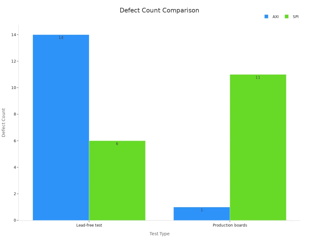
You can see x-ray finds all defects in some tests. SPI finds most but not all. Using both gives you strong quality control. You can trust your process to catch both hidden and easy-to-see problems.
In-Circuit and Functional Testing
After checking, you need to test your boards. In-circuit testing checks each part and connection on the pcb. You use probes to measure voltage, resistance, and current. This finds shorts, open spots, and wrong parts. In-circuit testing finds about 98% of faults. You can fix problems before boards leave the factory.
Functional testing checks if the pcb works as it should. You pretend to use the board and watch what happens. You measure signals, check voltages, and test with a load. This finds problems that only show up when the board is on. Functional testing makes your products work better.
-
You plan your tests and set up tools.
-
You do visual checks and write down results.
-
You look at failures and fix boards.
-
You make sure each pcb is good before shipping.
Functional testing needs special tools and can take more time. Still, it is very important for quality. You find problems that other tests might miss.
Process Control and Traceability
You keep your process steady by watching every step. Process control means you check things like solder heat, trace width, and humidity. You use SPC to see trends and fix problems early. You set limits, like ±0.02 mm for trace width, to keep things steady.
Traceability lets you track each pcb from start to finish. You write down batch numbers, material papers, and test results. If you find a problem, you can trace it back and find out why. You use FAI to check new batches and keep records for every group.
-
You keep your work area neat and clean with 6S.
-
You watch temperature and humidity all day to stop defects.
-
You use steps to keep bad items out of production.
-
You train your team and check work often to keep quality high.
-
You follow ISO 13485 and other rules to stop defects and recalls.
Modern pcb inspection, process control, and traceability work together. You get better boards, fewer problems, and more trust from customers. You can use AI and IoT tools to watch in real time and find problems early. These steps help you make good pcb products that meet industry rules.
Reliability and Standards
Common Defects
It is important to know about common defects in PCB assembly. These problems can make your products not work well. Most defects happen while making the board. If you find these problems early with pcb inspection, you can fix them fast. This stops bigger problems later.
Here is a table that lists some common defects. It shows what each defect means and how it can hurt your product:
|
Defect Name |
Description |
Impact on Product Performance |
|---|---|---|
|
Plating Voids |
Gaps in metal coating |
Open circuits, reliability issues |
|
Bad Soldering |
Poor heating or contamination |
Connection problems, possible failure |
|
Solder Bridges |
Unwanted solder between joints |
Short circuits, board damage |
|
Tombstoning |
One side of a part lifts off the board |
Open circuits, rework needed |
|
Board bends or twists |
Solder issues, poor assembly |
|
|
Solder Ball/Solder Dreg |
Small solder balls left on the board |
Short circuits, appearance problems |
|
Offset |
Pins do not line up with pads |
Poor electrical properties, bad solder |
|
Missing |
Parts not placed on the board |
Open circuits, device does not work |
|
Wrong Parts |
Incorrect parts used |
Function and reliability problems |
You should use pcb inspection at every step to find these defects. Checking often helps keep your boards safe and working right. If you see problems like solder cracks or dirt, you can change your process. This makes your product better.
Tip: Always look for defects like solder bridges, missing parts, or warpage during pcb inspection. Finding problems early saves time and money.
Industry Standards
You need to follow industry standards to make sure your PCB assemblies are good. Standards help you control your process and make better products. Some important standards are:
-
IPC-A-610: This standard shows what good electronic assemblies look like. It covers things like soldering, where parts go, and how clean the board is.
-
ISO 9001: This quality rule helps you set up strong control systems. It tells you to keep records, train workers, and check your process.
-
UL Certification: This safety mark means your boards meet tough safety rules.
-
RoHS Compliance: This rule limits the use of dangerous materials in electronics.
You should use these standards to guide your pcb inspection and quality checks. When you follow them, your products last longer and work better. Standards also help you earn trust from customers.
Note: Following industry standards makes your inspection stronger and helps you avoid costly mistakes.
Knowing how to do each step in electronics manufacturing helps you make good circuit boards. If you learn how to read inspection reports and test results, you can make smart choices about quality.
-
Look at inspection reports to see if parts are in the right place and if solder joints look good. Check if the board is in good shape.
-
Use AOI and X-ray machines to find problems you cannot see with your eyes.
-
Pick companies that have good quality checks and the right certificates.
Good quality control means you will have fewer mistakes and stronger products. Always check your work and ask experts for help to get the best results.
FAQ
What is the difference between SMT and THT?
SMT puts parts on the surface of the board. THT puts part leads through holes in the board. SMT works well for small, light parts. THT gives strong support for heavy or stressed parts.
How do you check for defects in PCB assembly?
You use tools like AOI, X-ray, and in-circuit testers. These tools help you find missing parts, bad solder joints, or hidden problems. You can spot most defects before the boards leave the factory.
Why is cleaning important after soldering?
Cleaning removes leftover flux and dirt. Clean boards last longer and work better. Dirt or residue can cause short circuits or corrosion. You should always check for clean surfaces before moving to the next step.
What standards should you follow for PCB assembly?
You should follow IPC-A-610 for assembly quality. ISO 9001 helps you set up good quality systems. UL and RoHS make sure your boards are safe and free from harmful materials.


